3.6.3 GAS REGULATION CHECK
Supply pressure check
1. Loosen screw “1” (Fig. 3.33) and connect the pressure gauge
connection pipe into the test point.
2. Turn the boiler on at maximum power, enabling the “flue sweep”
function (press the key for 5 seconds and then press the
programming keys and together ensuring the dashes are
at the top of the display (see Fig. 3.30). The supply pressure
should correspond to that shown for the type of gas the boiler is
designed for methane gas G20 (see table below).
3. Disable the test mode by pressing the reset key.
4. When the check is over, tighten screw “1” and test for tightness.
NOTE:IF THE WORKING PRESSURE IS INSUFFICIENT CHECK THE GAS
METER, METER GOVERNOR, OR INSTALLATION PIPEWORK FOR
ERROR.
IMPORTANT!
DO NOT PROCEED CHECKING AND ADJUSTING THE CO2 SETTINGS
UNLESS THE WORKING PRESSURE IS ADEQUATE.
NOTE:ALL SETTINGS ARE TO BE MADE WITH A CO2 METER WITH THE
PROBE FITTED TO THE FLUE GAS ANALYSIS POINT.
Setting the CO2 at minimum power
To check the air/gas ratio at minimum power, proceed as follows:
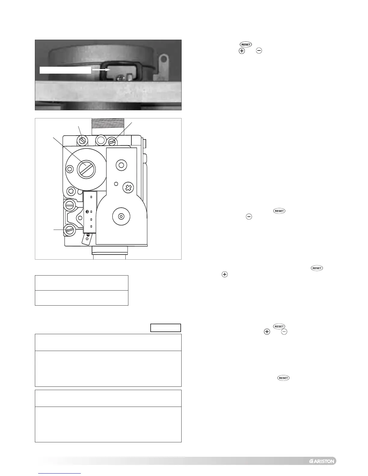
1. Connect the combustion analyser to the analysis point (Fig.
3.32) after removing the cover plate.
2. Set the boiler to minimum power via the test function (see
paragraph 3.6.1) or by pressing the button for 5 seconds
and then pressing the button on the control panel, ensure
the dashes are at the bottom of the display (see Fig. 3.30).
Ensure the CO2 value on the analyser corresponds with the
value indicated in
table 4D. If this is not the case, adjust screw
“2” (Fig.3.33) with a screwdriver in small intervals, allowing the
reading to become stable before adjusting further, until you
obtain the correct CO2 reading. Allow the reading to become
stable for at least 4 minutes.
3. When the check is over, replace the cap on screw “2” (Fig. 3.33).
4. Disable operation at minimum power by pressing the key
or press the key to check the maximum value (dashes at top
of display see Fig. 3.31).
While the appliance is operating at maximum power, check
the gas rate of the appliance at the gas meter
Setting the CO2 at maximum power
To check the air/gas ratio at maximum power, proceed as follows:
1. With the combustion analyser already connected to the analysis
point, set the boiler to maximum power via the test function (see
paragraph 3.6.1) or by pressing the button for 5 seconds
and then the programming keys and ensuring the dashes
at the top of the display (see Fig. 3.30).
Ensure the CO2 value on the analyser corresponds with the
value indicated in table 4D
. If this is not the case, adjust screw
“4” with a screwdriver in small intervals allowing the analyser
reading to stabilise before adjusting further (Fig. 3.33), until you
obtain the correct CO2 reading. Allow the reading to become
stable for at least 4 minutes.
2. Disable the test mode by pressing the button.
The test mode is automatically disabled after 5 minutes.
3. Repeat the air/gas ratio at minimum power check (see
above).
4. Disconnect the analyser, remount the cover plate and check it is
securely in place.
While the appliance is operating at minimum power, check
the gas rate of the appliance at the gas meter
NOTE:WHEN MAKING ADJUSTMENTS, ADJUST SMALL AMOUNTS AND
WAIT FOR THE ANALYSER TO STABILISE BEFORE MAKING
FURTHER ADJUSTMENTS.
CO2 SETTING MAXIMUM VALUE
CO2 at maximum power % vol 8.7 ±0.2 (NG)
% vol 10.2 ±0.2 (LPG)
CO2 SETTING MINIMUM VALUE (NAT GAS)
CO2 at minimum power % vol 9.2 ±0.2 (NG)
% vol 10.6 ±0.2 (LPG)
SETTING THE GAS PRESSURES
FIG. 3.32
FIG. 3.33
TABLE 4D
Analysis cover plate
 Loading...