55
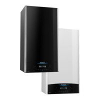
FIG. 7.9
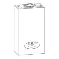
FIG. 7.10
H
G
I
I
1. Disconnect the electrical connector “G” (FIG. 7.9);
2. Disconnect the compensation tube “H” (FIG. 7.9);
3. Unscrew the two screws “I” (FIG. 7.10);
4. Remove the Air Pressure Switch
7.3.2. REMOVING THE AIR PRESSURE SWITCH 7.3.3. REMOVING THE BURNER
With the fan removed (see Section 7.3.1);
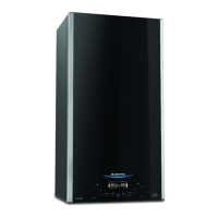
1. Remove the four allen screws “J” (FIG. 7.11);
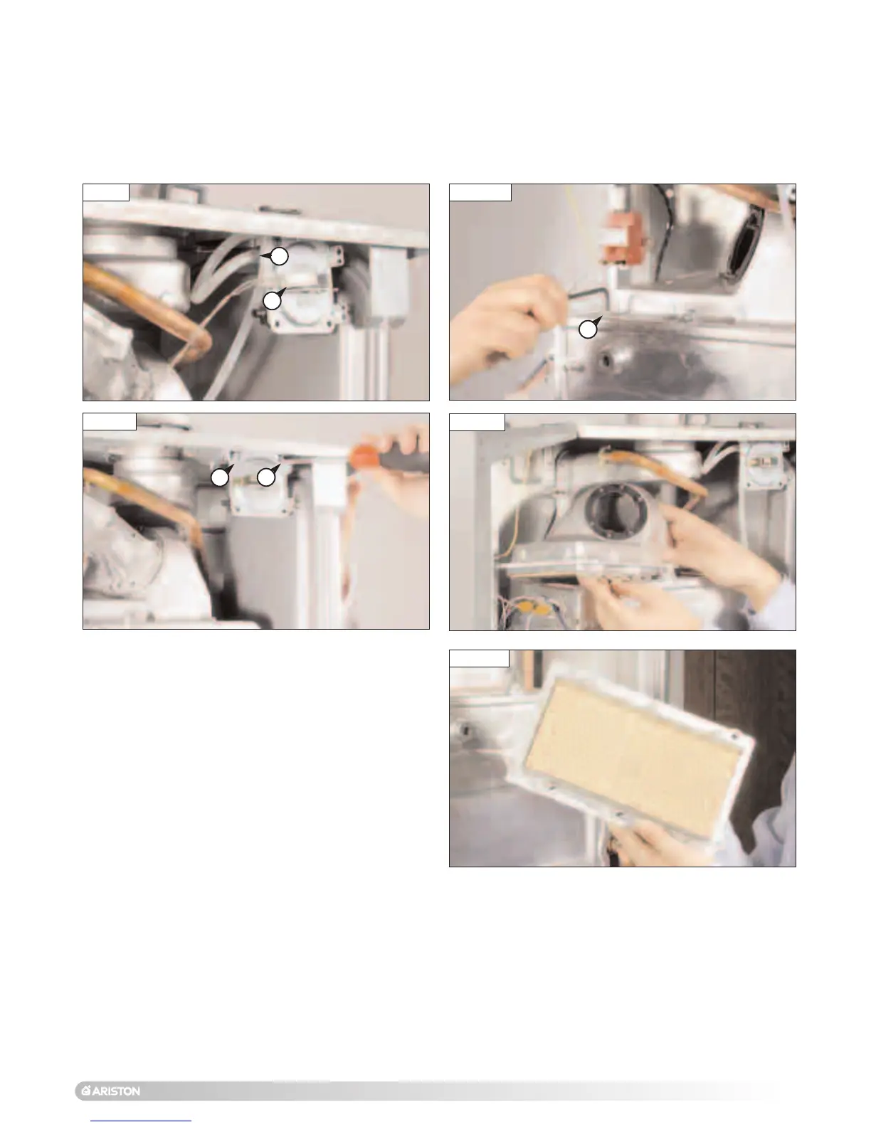
2. Slide the burner from its housing (FIG. 7.12 - 7.13).
FIG. 7.11
FIG. 7.12
FIG. 7.13
J
 Loading...