EasyManuals Logo

Ariston ACO 32 RFFI SYSTEM User Manual

Ariston ACO 32 RFFI SYSTEM
80 pages
To Next Page IconTo Next Page
To Previous Page IconTo Previous Page
Page #8 background imageLoading...
Page #8 background image
8
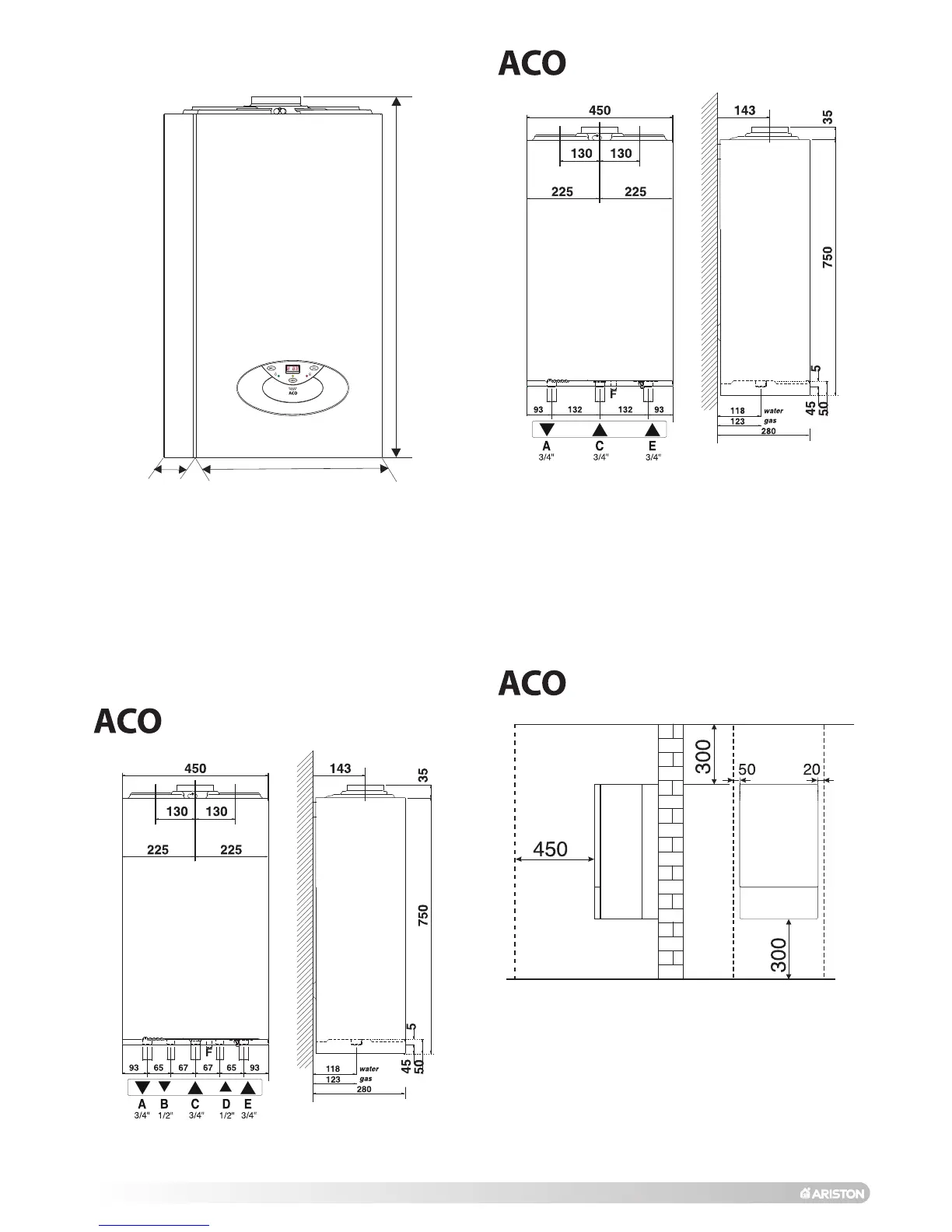
2.3. OVERALL DIMENSIONS
In order to allow access to the interior of the boiler for maintenance
purposes, the boiler must be installed in compliance with the
clearance requirements indicated in the diagram below.
2.4. MINIMUM CLEARANCES
LEGEND:
A = Central Heating Flow (3/4”) (22mm Copper Tail)
B = Domestic Hot Water Outlet (1/2”) (15 mm Copper Tail)
C = Gas Inlet (3/4”) ( 22mm Copper Tail)
D = Domestic Cold Water Inlet (1/2”) (15mm Copper Tail)
E = Central Heating Return (3/4”) (22mm Copper Tail)
F = Condensate discharge
SV outlet = 1/2” Female BSP (Not Shown)
785
280
450
27/32 MFFI (COMBI)
27/32 MFFI/RFFI
FIG. 2.0
FIG. 2.2
27/32 RFFI (SYSTEM)
FIG. 2.1
FIG. 2.3

Questions and Answers:

Question and Answer IconNeed help?

Do you have a question about the Ariston ACO 32 RFFI SYSTEM and is the answer not in the manual?

Ariston ACO 32 RFFI SYSTEM Specifications

General IconGeneral
BrandAriston
ModelACO 32 RFFI SYSTEM
CategoryBoiler
LanguageEnglish

Related product manuals