62
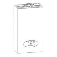
7.5.6. REMOVING THE PUMP
1. Unplug the electrical connection “A7” (FIG. 7.48);
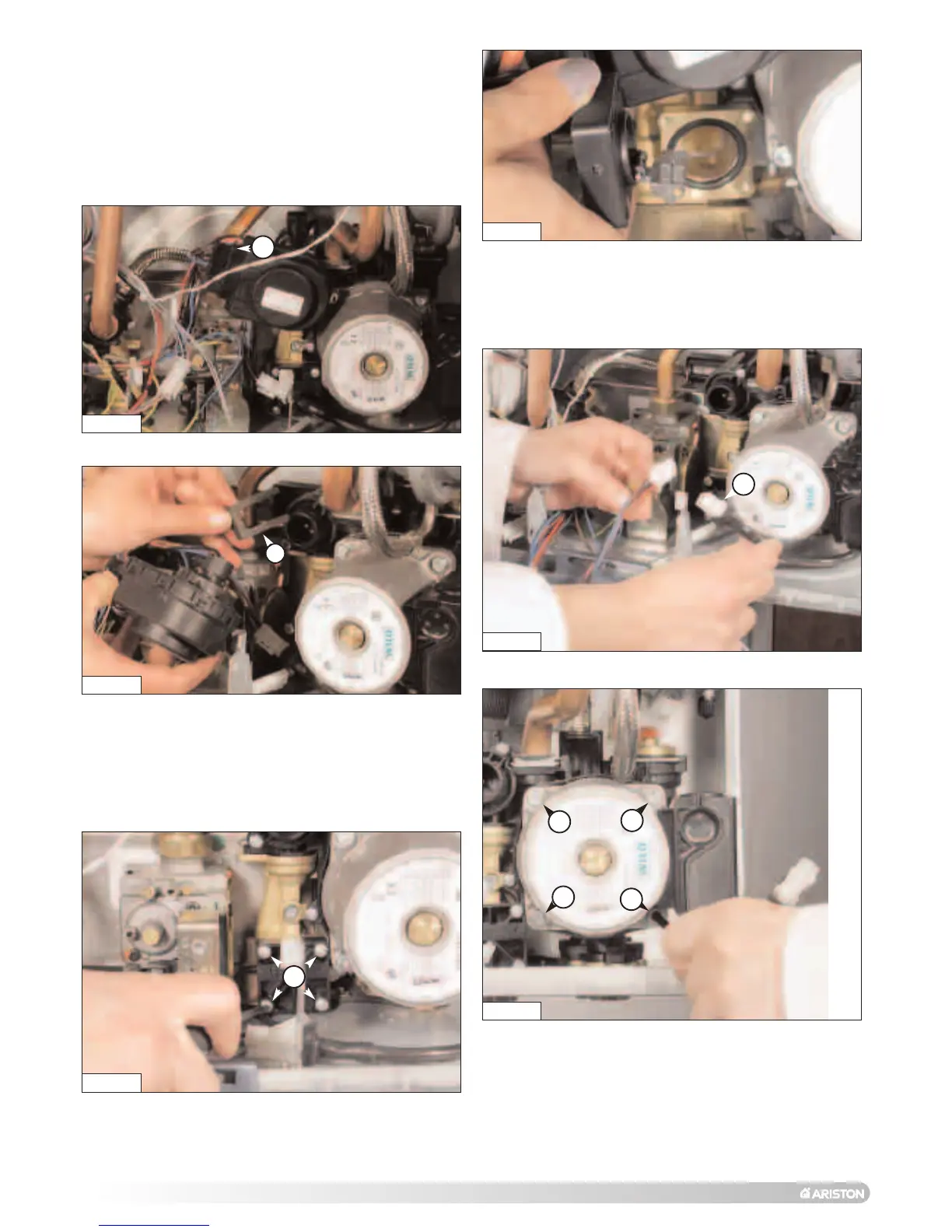
2. Unscrew the four screws “A8” (FIG. 7.49);
3. Remove the pump (FIG. 7.50).
FIG. 7.48
FIG. 7.49
A7
A8
A8
A8
A8
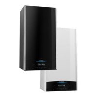
A6
7.5.5. REMOVING THE D.H.W. FLOW SWITCH
(MFFI ONLY)
1. Unplug the electrical connector;
2. Unscrew the four screws “A6” (FIG. 7.46);
3. Remove the D.H.W. flow switch (FIG. 7.47).
FIG. 7.46
FIG. 7.47
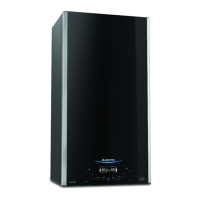
A5
FIG. 7.44
7.5.4. REMOVING THE DIVERTER VALVE ACTUATOR
1. Unplug the electrical connector “A4” (FIG. 7.44);
2. Release the retaining clip “A5” and remove the diverter
valve actuator (FIG. 7.45).
FIG. 7.45
A4
 Loading...