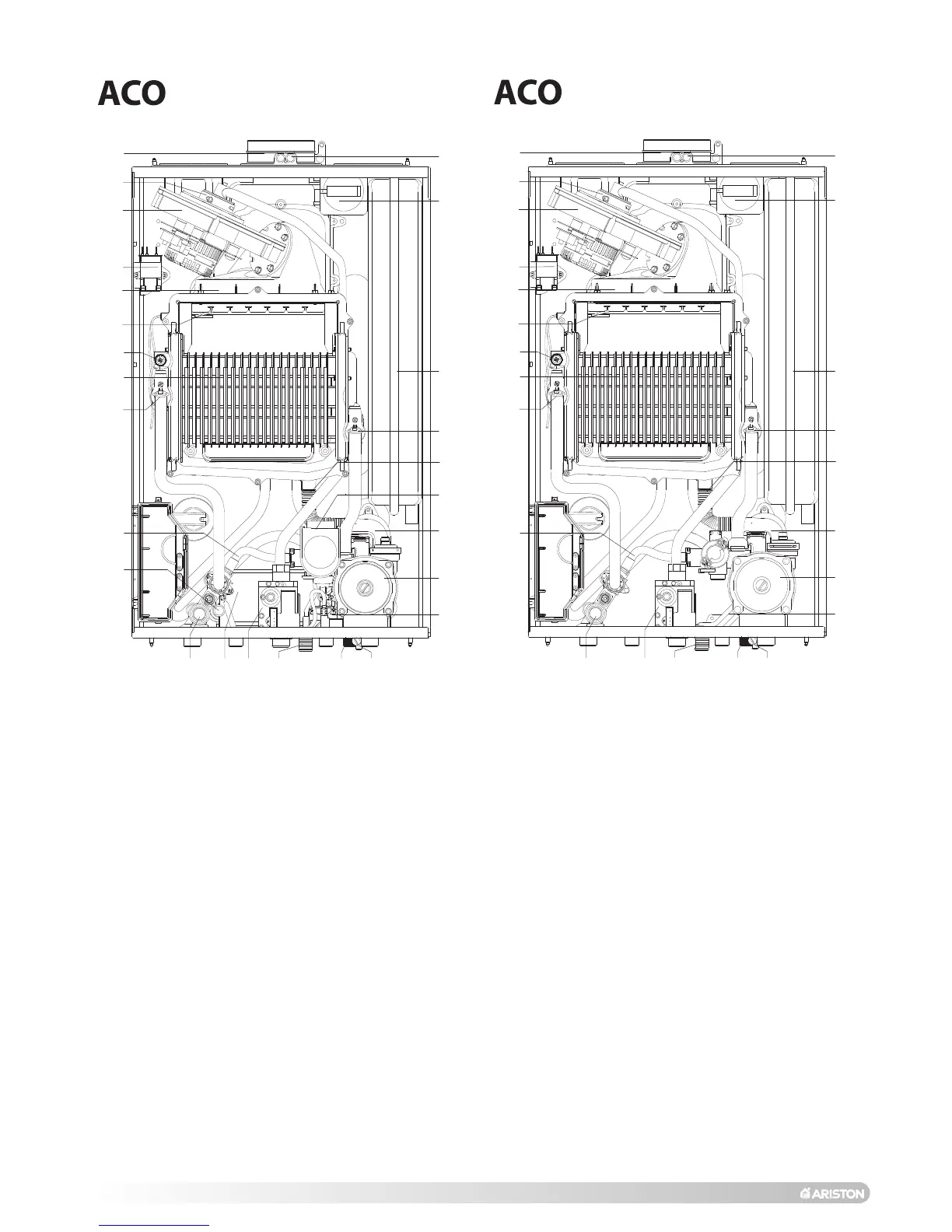
EasyManuals Logo

Ariston ACO 32 RFFI SYSTEM User Manual

Ariston ACO 32 RFFI SYSTEM
80 pages
To Next Page IconTo Next Page
To Previous Page IconTo Previous Page
Page #6 background imageLoading...
Page #6 background image
6
LEGEND:
1. Flue connector
2. Mixer
3. Fan
4. Spark generator
5. Burner
6. Ignition and detection electrode
7. Air release valve
8. Main heat exchanger (aluminium)
9. Central Heating flow temperature probe
10. Automatic by-pass
11. Domestic Hot Water temperature probe
12. Safety valve (3 bar)
13. Secondary heat exchanger
14. Gas valve
15. Condensate discharge
16. Condensate trap inspection cap
17. Drain valve
18. Domestic Hot Water flow switch
19. Circulation pump with automatic air release valve
20. Condensate trap
21. Diverter valve
22. Condensate trap (tube)
23. Central Heating return temperature probe
24. Expansion vessel
25. Air pressure switch
26. Combustion analysis test point
1.3. OVERALL VIEW
9
8
1
3
5
7
10
11
12 13 14 15 16
19
21
24
25
6
4
26
20
17
18
23
2
22
27/32 MFFI (COMBI)
FIG. 1.0
9
9
88
1
1
3
3
5
5
77
10
12 14 15 16
19
24
25
6
6
4
4
26
20
17
18
23
2
2
22
27/32 RFFI (SYSTEM)

Questions and Answers:

Question and Answer IconNeed help?

Do you have a question about the Ariston ACO 32 RFFI SYSTEM and is the answer not in the manual?

Ariston ACO 32 RFFI SYSTEM Specifications

General IconGeneral
BrandAriston
ModelACO 32 RFFI SYSTEM
CategoryBoiler
LanguageEnglish

Related product manuals