48
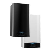
4. ZONE VALVES
The boiler can be connected to a central heating system that uses
two zone valves allow connection to an indirect storage cylinder.
There are two possible types of wiring diagram, one for the
connection to an Unvented Cylinder (Diagram. A, page 49) and one
for connection to an open vented cylinder (Diagram B, page 50).
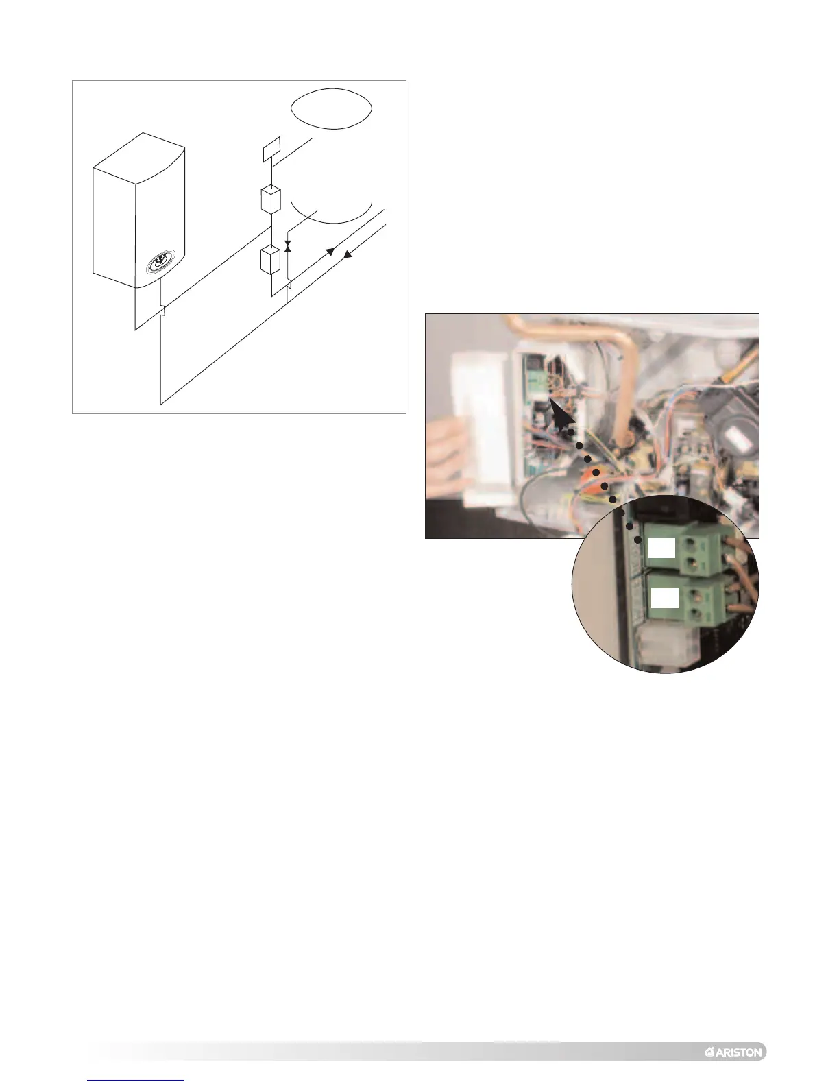
In both cases the boiler connection is shown as TA, which relates to
the terminal on the PCB for external controls (see FIG. 4.2).
When connecting the boiler to an external cylinder it is necessary to
remove the integral clock from the boiler (see SECTION 7.6.3), do not
run 240V cables and the TA cables together, use separate cables to
prevent induced voltage on the low voltage switching circuit.
NOTE:THE USE OF A ‘Y’ PLAN SYSTEM IS NOT POSSIBLE WITH THE ACO
BOILER DUE TO THE LOW VOLTAGE SWITCHING OF THE APPLIANCE.
FIG. 4.1
TA
SP
FIG. 4.2
IMPORTANT!!
ENSURE THAT A BALANCING VALVE IS FITTED ON THE CYLINDER RETURN
AND BALANCED CORRECTLY AT COMMISSIONING STAGE.
 Loading...