13
inner aluminium exhaust flue.
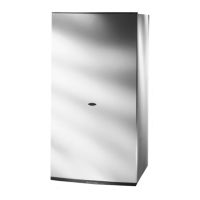
To connect the vertical flue kit directly to the boiler, place
the adaptor
(see FIG 2.12) (supplied with vertical flue kit)
onto the exhaust manifold and secure with the clamp, the
vertical flue kit must then be inserted through the roof
flashing, this will ensure that the correct clearance above
the roof is provided as the terminal is a fixed height.
Should extensions be required, they are available in 1
metre
(Part No. 705786), 500mm (Part No. 705790) and
160mm lengths (Part No. 705812), they must be
connected directly to the boiler and secured with the clamp
supplied before connecting the adaptor to allow the
vertical flue kit to be fitted. In the event that extension
pieces need to be shortened, they must only be cut at the
male end and it must be ensured that the distance
between the inner and outer flue are kept (Fig. 2.10).
When utilising the vertical flue system, action must be
taken to ensure that the flue is supported adequately to
prevent the weight being transferred to the appliance flue
connection.
When the flue passes through a ceiling or wooden floor,
there must be an air gap of 25mm between any part of the
flue system and any combustible material. The use of a
ceiling plate will facilitate this. Also when the flue passes
from one room to another a fire stop must be fitted to
prevent the passage of smoke or fire, irrespective of the
structural material through which the flue passes.
FITTING THE FLUE (TWIN PIPE)
Where it is not possible to terminate the flue within the
distance permitted for coaxial flues, the twin flue pipe can
be used by fitting a special adaptor to the flue connector
and using the aperture for the air intake located on top of
the combustion chamber.
Considerations necessary for twin flue installation;
It is most important to avoid any possible condense
formation entering the appliance.
According to Table 2.1
(Page 16) decide if condensation
will form within the flue. If yes, there are two options;
1) Where condense will form but can be negated with
insulated flue, install insulated the flue with a fall of 5mm in
every metre away from the boiler.
2) The exhaust flue will have a fall of 3
o
back to the boiler
and a suitable trap will be fitted on the exhaust as close
to the boiler as possible, condense will then be suitably
disposed of.
Where the flue runs through cold spots, i.e. loft areas,
condense is likely to be formed, therefore a fall back to the
boiler and a trap is required.
Always ensure that the flue is adequately supported,
avoiding low points. (MTS supply suitable clamps as Part
No. 705778).
IMPORTANT!
FOR ALL FLUE SYSTEMS, A
RESTRICTOR MAY NEED TO BE
INSERTED INTO THE EXHAUST
MANIFOLD
, THE SIZE OF THE
RESTRICTOR AND DETAILS OF FITTING
REQUIREMENTS ARE SHOWN IN TABLE
2.1 (PAGE 16).
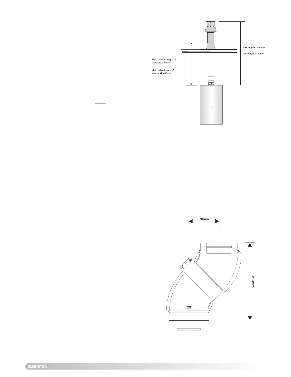
FIG 2.15
FIG 2.16
Minimum offset distance when using 2x 45
o
bends

 Loading...