19
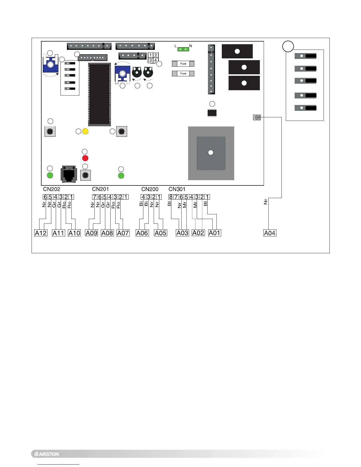
2.13 ELECTRICAL/SYSTEM DIAGRAMS
B - Central Heating Temperature Adjustment
C - Connector for Remote Control (Climate Manager)
D - Domestic Hot Water Temperature Adjustment
E - Soft-light Adjustment
F - Maximum Heating Adjustment
G - Time Clock Connector
H - On/Off Switch
I - Fume Sensor L.E.D.
J - Central Heating Selector
K - Ignition Failure (Lockout) L.E.D.
L - On/Off L.E.D.
M - Reset Button
N - Central Heating L.E.D.
O - Transformer
P - Spark Generator I.C.
Q- Gas Valve Relay
R - Circulation Pump Relay
S - Fan Relay
A01 - Circulation Pump
A02 - Fan
A03 - Spark Generator/Gas Valve Supply
A04 - Detection Electrode
A05 - Main Circuit Temperature Probe
A06 - Domestic Hot Water Temperature Probe
A07 - D.H.W. Flow switch
A08 - Pump Pressure Switch
A09 - Modulator
A10 - Air Pressure Switch
A11 - Safety Thermostat
A12 - External (Room) Thermostat
COLOURS:
Gr - Grey
Bi - White
Rs - Red
Mr - Brown
Bl - Blue
Nr - Black
Ro - Pink
A - Jumper:
1 - Don’t move (jumper is factory set in position B)
2 - Anti-cycling Device Adjustment for Heating
Position A = 0 mins Position B = 2 mins
3 - Don’t move (jumper is factory set in position B)
4 - Don’t move (jumper is factory set in position B)
5 - Fan/Pump over-run selector
Position A = OFF Position B = ON
FIG. 2.22

 Loading...