17
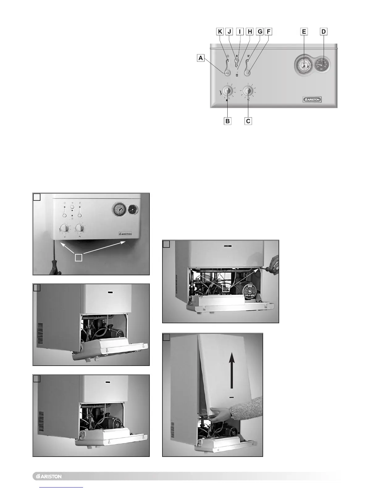
In order to access the inside of the boiler, it is necessary to unscrew
the fastening screws “A” of the control panel located on the lower part
of the panel itself.
The control panel moves downward and when pulled forward rotates
on two lateral hinges.
The panel stays in a semi-horizontal position, which allows access to
the inner parts of the boiler.
In order to increase the manouvering space, it is possible to raise the
control panel and rotate it to a fully horizontal position.
2.11 REMOVING THE
FRONT PANEL
B
1
2
3
4
5
A
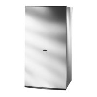
LEGEND:
A - On/Off button
B - Central heating temperature adjustment
C - Domestic hot water temperature adjustment
D - Heating system pressure gauge
E - Time clock
F - Central heating selector
G - Central heating L.E.D. (green)
H - Flue sensor L.E.D. (yellow)
I - Overheat and/or ignition failure (lockout) L.E.D. (red)
J - Ignition failure (lockout) and/or overheat reset
button/Flue Test analysis mode*
K- ON/OFF L.E.D. (green)
2.10 CONTROL PANEL
FIG. 2.20
To dismantle the front
casing panel it is necessary
to:
1 - Remove the two screws
“B”;
2 - Move the front casing
panel up and lift forward.
FR019A
* Warning the flue analysis mode must only be selected by a
qualified service engineer.

 Loading...