ARKEL Elektrik Elektronik Ltd. Şti. www.arkel.com.tr
ARKEL 40 KM-20
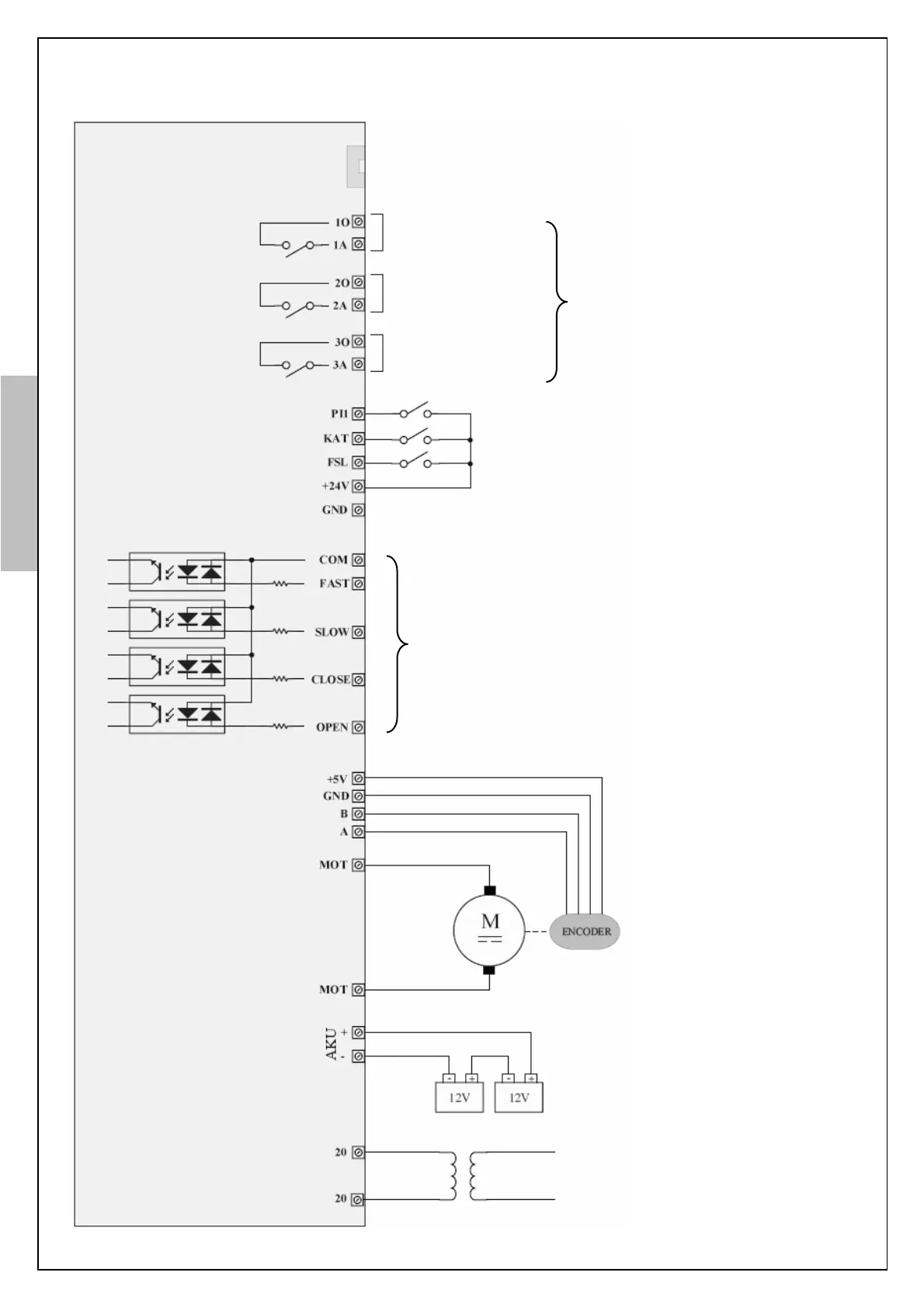
7. CONNECTION DIAGRAM
Additional door opening zone signal input
+5Vdc operation voltage
100-2048 pulse
2-channel encoder
24V DC geared motor, max. 8A
Outputs to lift control mainboard
(Max. 3A @ 250VAC or 30VDC)
Note: The relay contacts must not be
used as safety contact in the safety
circuit of the elevator!
24V DC emergency supply
(with 2 pcs. 12V/1.2Ah battery or
external supply)
Min. trans. power = 10VA + motor power
Internal supply
24VDC / 0.1A
Figure-3: Connection diagram
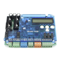
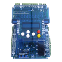
KM-20 Keypad connection (Optional)
Inputs from lift control system
Can be supplied with internal or external 24Vdc.
Refer to Figure-4 and Figure-5
(Inputs are activated with 24VDC internal supply)
Note: For V1.9 and higher version controllers,
positive or negative common is selectable.