Armstrong International
221 Armstrong Blvd, Three Rivers, MI 49093 - U.S.A.
Tel: (269) 279-3602 Fax: (269) 279-3130
Designs, materials, weights, and performance ratings are
approximate and are subject to change without notice.
Visit armstronginternational.com for the most updated information.
Page 19 of 36
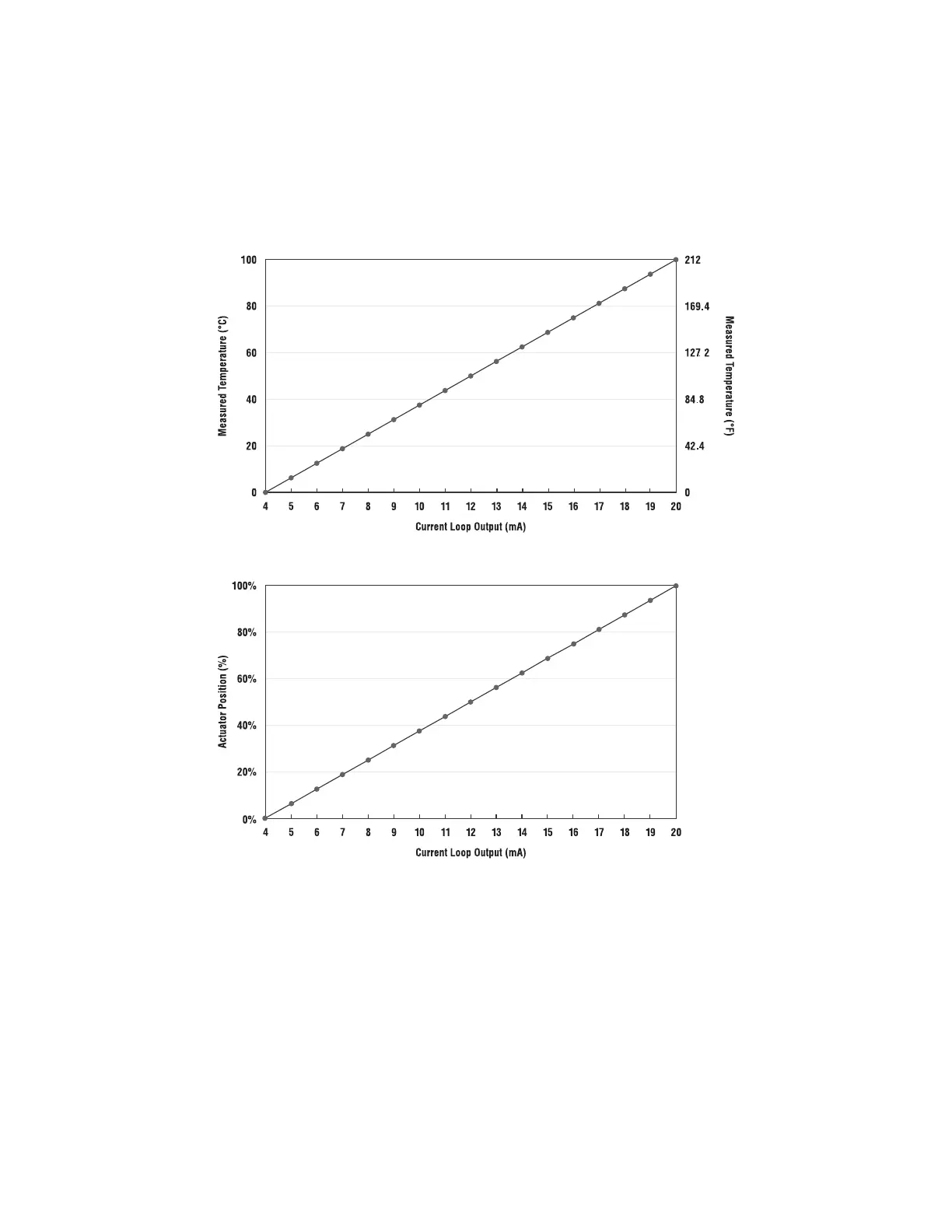
4.3 - Standard G2 Current Loop Output Characteristic
4.0 - Current Loop I/O, cont.
The G1 unit will deliver a current loop output (feedback signal) according to the graphs below. If feedback is required (such as external
monitoring), calibrate the current loop receiver (external PLC or controller) according to Fig: 4.3 and Fig. 4.4.
In Temperature Mode, the Actuator will output the current temperature being sensed by the Emech® Temperature Sensor and transmit
according to the scale shown in Fig. 4.3.
In Positioner Mode, the Emech
®
actuator has very precise rotational control step resolution of 0.07-0.8 degree rotation for the G12 and G13
respectively for a 0.12mA input increment change;
While the actuator will respond to a minimum 0.12mA loop input change and rotate the actuator at a 0.07 degrees rotation movement,
the Position Feedback Confirmation mA loop output signal back from the Actuator to the PLC, which confirms the actuator shaft position,
as the actuator has an independent confirmation via a lower resolution optical encoder as compared to the stepper motor increments, the
confirmation back to the PLC is only approximately every 6 degrees of rotation. Figure 4.
As can be obtained from the above graphs, the full control range in either Temperature control (0-100°C or 32-212°F) or Position Control
(0-100%) corresponds to a Loop Output range of 5 to 19 mA (linear response). This has been implemented to obtain the same output loop
signal as the input loop=controlling signal when the Actuator is in control.
A loop signal output of 20 mA indicates an error condition. Check the Actuator display for the error number, and see section 6.6 for error
code definitions.
Continued on next page
Figure 4.3 Temperature Control
Figure 4.4 Positioner Control