Armstrong International
221 Armstrong Blvd, Three Rivers, MI 49093 - U.S.A.
Tel: (269) 279-3602 Fax: (269) 279-3130
Designs, materials, weights, and performance ratings are
approximate and are subject to change without notice.
Visit armstronginternational.com for the most updated information.
Page 10 of 36
!
!
!
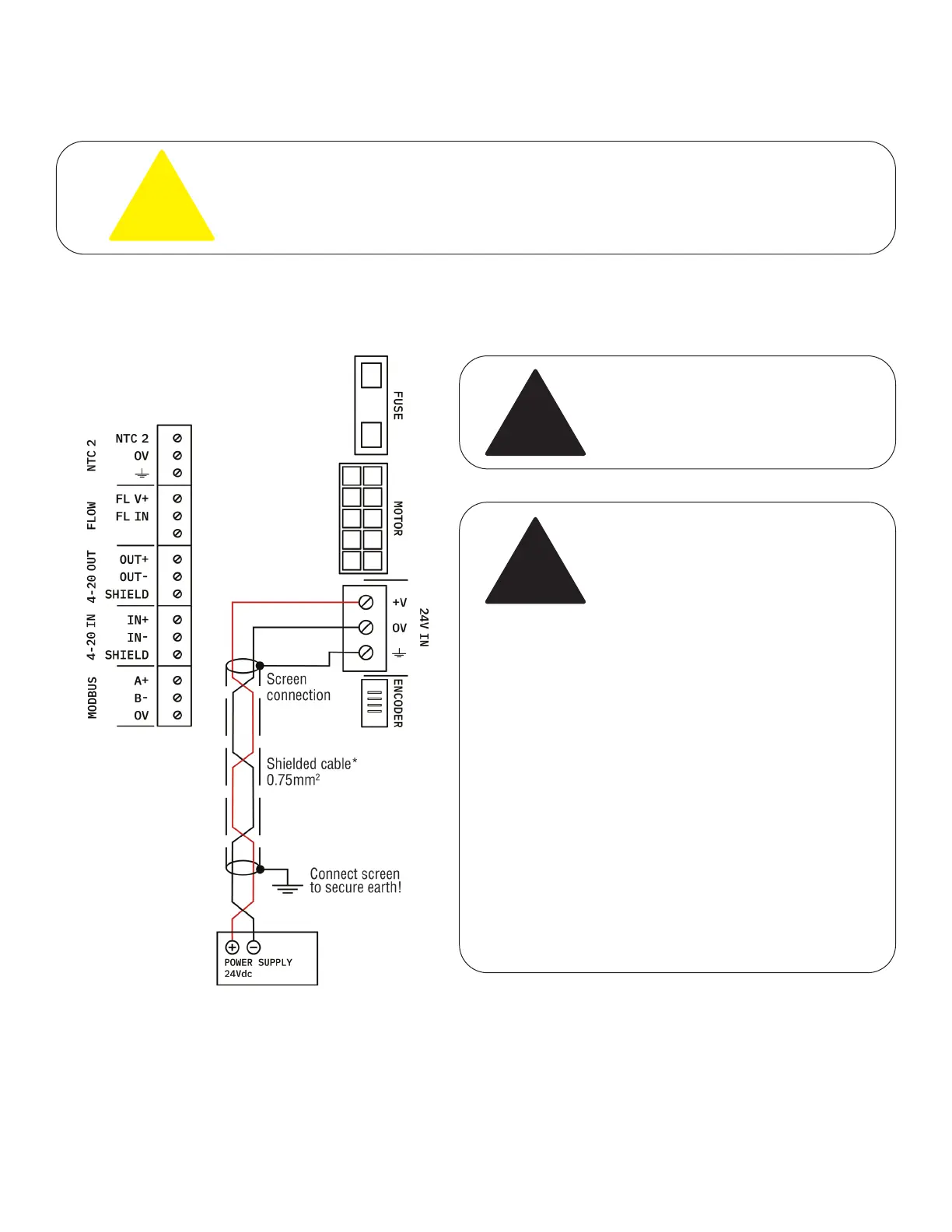
3.2 - Wiring Instructions
Wire the supply connections as indicted below using the correct diameter shielded cable. When placing the wiring in metal conduit, which
is earthed, shielded cable is not required.
WIRE THE SUPPLY FIRST (before making any other connections). Ensure that the actuator supply
consists of a 24VDC supply (not AC) and that the voltage tolerances are within the permissible voltage
limits of the actuator.
SWITCH THE SUPPLY OFF BEFORE CONNECTING!
3.0 - Electrical Installation, cont.
3.2.1 - Wiring Instructions
Ensure conduits and wire screens are
properly grounded to reduce possible
effects of EM (Electromagnetic Interference)
on actuator operation.
Refer to Table 3.1 as a guide for wiring cable lengths and voltage drops.
WARNING!
When the actuator is wired to the power
supply, it is important that the voltage drop
to the actuator remains no more than 1-2
Volts when the actuator is operating under
load.
To check this, put a meter on the DC supply
terminals at the unit, and measure the
24VDC supply. Keeping the meter in place,
use the manual handle to move the valve
out of position, or change a set value so the
actuator is instructed to move.
IF YOU OBSERVE GREATER THAN 2 VOLTS
DROP ON THE POWER SUPPLY AT THE
ACTUATOR WHEN OPERATING, PLEASE
REVIEW AND INCREASE WIRE DIAMETER
BEING UTILIZED TO MINIMISE VOLTAGE
DROP OVER DISTANCE OF CABLE RUN.
EXCESSIVE VOLTAGE DROP AT THE
ACTUATOR UNDER LOAD CAN LEAD
TO UNRELIABLE PERFORMANCE AND
POTENTIALLY PERMANENT DAMAGE TO
THE INSTALLED UNIT.
Continued on next page