Armstrong International
221 Armstrong Blvd, Three Rivers, MI 49093 - U.S.A.
Tel: (269) 279-3602 Fax: (269) 279-3130
Designs, materials, weights, and performance ratings are
approximate and are subject to change without notice.
Visit armstronginternational.com for the most updated information.
Page 11 of 36
3.2.2 - Power Supply Wire Specification
3.0 - Electrical Installation, cont.
Consider the minimum cross sectional area and length of the supply cable such that the voltage drop across the total cable length remains
within the permissible voltage tolerance of the actuator. For example when using a 0.75mm2 cable, the voltage drop will be a 1.2V at 3A
and 10m length, which is 5% of the 24V supply. Use the table 3.1 below as a guide to determine cable size and maximum length.
Table 3.1: Cable Length (depending on cable area and actuator model)
G22 35Nm Area Resistance Drop Recommended Maximum Absolute Maximum
AWG mm2 m0hm/ft m0hm/m V/ft V/m ft m ft m
20 0.5 0.021 0.07 0.064 0.21 19.7 6 38.0 11.6
18 0.75 0.015 0.05 0.043 0.14 29.5 9 56.7 17.3
-- 1.0 0.009 0.03 0.030 0.10 39.4 12 78.8 23.1
16 1.5 0.006 0.02 0.213 0.07 55.8 17 113.8 34.7
-- 2.0 0.006 0.02 0.015 0.05 75.4 23 151.5 46.2
14 2.5 0.003 0.01 0.012 0.04 95.1 29 189.6 57.8
G23 100Nm Area Resistance Drop Recommended Maximum Absolute Maximum
AWG mm2 m0hm/ft m0hm/m V/ft V/m ft m ft m
18 0.75 0.015 0.05 0.070 0.23 16.4 5 34.1 10.4
-- 1.0 0.009 0.03 0.052 0.17 23.0 7 45.6 13.9
16 1.5 0.006 0.02 0.037 0.12 32.8 10 68.2 20.8
-- 2.0 0.006 0.02 0.027 0.09 45.9 14 90.9 27.7
14 2.5 0.003 0.01 0.021 0.07 55.8 17 113.8 34.7
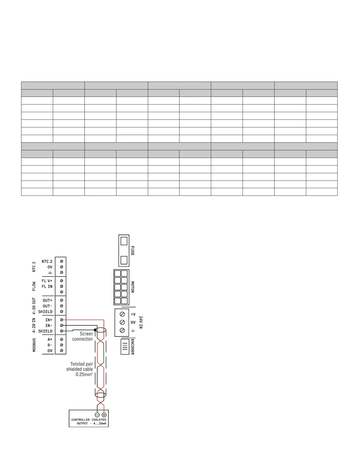
3.2.3 - Wiring of Actuator mA Loop Reciever
To comply with EMC (Electro Magnetic Compatibility) standards, the wiring must be placed in the conduit (must be connected to earth
ground) and shielded twisted pair cable (0.25mm
2
) should be used (see Figure 3.3 below).
Figure 3.3
Controller with isolated output