EasyManuals Logo

ARRI ALEXA Mini Quick Guide

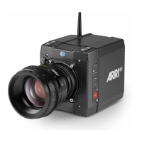
ARRI ALEXA Mini
76 pages
To Next Page IconTo Next Page
To Previous Page IconTo Previous Page
Page #22 background imageLoading...
Page #22 background image
22 Connectors
7.2 I/O panel
NOTICE
If the power supply is interrupted with the camera switched on, the camera will
automatically repower and boot-up on reconnection.
1
3
2
4
5
6
7
1 Timecode connector 5 BAT main power in
2 White radio antenna 6 EXT connector
3 MVF-1 or CCP-1 7 Ethernet connector
4 HD-SDI image out 1 & 2
TC (5-pin LEMO)
The TC connector is a 5-pin LEMO socket. It accepts and distrib-
utes LTC (Longitudinal Time Code) signals.
Note: The camera has a TC buffer to keep a synced external TC
for up to three minutes while camera power is disconnected.
White radio antenna
Mounting point for white radio antenna for lens control.

Other manuals for ARRI ALEXA Mini

Questions and Answers:

Question and Answer IconNeed help?

Do you have a question about the ARRI ALEXA Mini and is the answer not in the manual?

ARRI ALEXA Mini Specifications

General IconGeneral
Sensor TypeALEV III CMOS
Dynamic Range14+ stops
Recording FormatsARRIRAW, ProRes
Power Input10.5-34 V DC
Base SensitivityEI 800
Lens MountPL mount
Weight2.3 kg
ISO Range160 to 3200
Frame Rates0.75 - 200 fps (depending on recording format and sensor mode)
Dimensions185 mm x 125 mm x 140 mm
Power ConsumptionApprox. 50 W
OutputsHD-SDI
Sensor SizeSuper 35 format

Related product manuals