Chapter 4: Install and connect your Telephony Modem
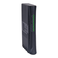
6. Link: Indicates Ethernet connectivity between the Telephony Modem and the computer.
7. Online: Indicates Internet data transmission status.
8. US: indicates upstream connectivity.
9. DS: indicates downstream connectivity.
10. Power: Indicates whether power is available to the device.
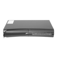
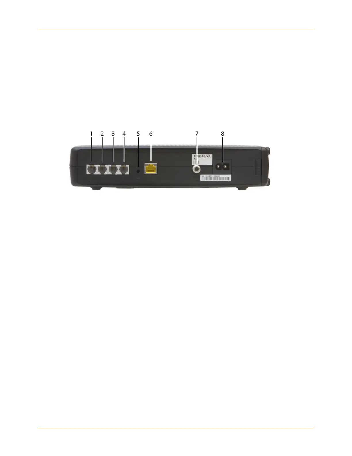
Rear panel
The rear of the Telephony Modem has the following connectors and controls.
1. Tel (1 - 2): Connector for the first phone line (or both lines of a 2-line phone).
2. Tel 2: Connector for the second phone line.
3. Tel (3 - 4): Connector for the third phone line (or both lines of a 2-line phone).
4. Tel 4: Connector for the fourth phone line.
5. Reset button: Resets the Telephony Modem as if you power cycled the device. Use a
pointed non-metallic object to press this button.
6. Ethernet connector: Connector for use with a computer LAN port.
7. Cable: Connector for the coaxial cable.
8. Power: Connector for the power cord.
Mount the Telephony Modem
You can either mount the Telephony Modem on a wall or place it on a desktop. For wall-
mount applications, you can mount the Telephony Modem with the indicators facing upward
(vertically) or to the side (horizontally).
Tools and materials
For wall-mounted installations, make sure you have the following tools and materials before
proceeding:
■
for mounting on drywall: Two 1/4” (6mm) drywall anchors (not included), two #6 x
1.5” (38.1 mm) self-tapping panhead screws (not included), and a drill with 1/4” (6mm)
bit (not included)
Touchstone TM804 Telephony Modem User Guide STANDARD Revision 1.2 24