Page 10 · 5400 Series TECSource User’s Manual
errors. See Working with RTDs below for more information. Only Sensor 1 has 4-
wire remote sense capability.
Using Remote TEC Voltage Sense
The Remote TEC Voltage Sense pins (2 & 9) are used to remotely measure the
TEC voltage. See Using Remote TEC Voltage Sense below for more information.
Using the TEC On LED
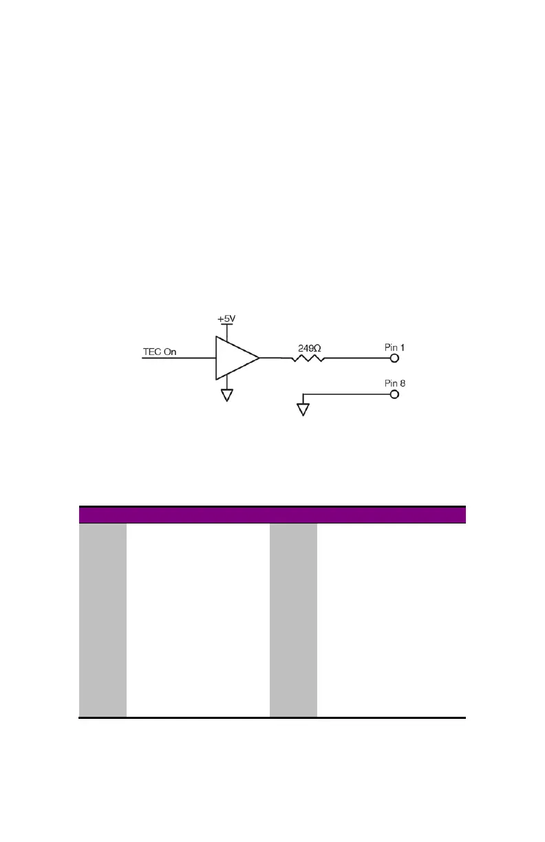
Pins 1 & 8 on the Output connector can be used to drive an LED to indicate
when the TEC is on. The signal is driven from a +5V buffer with a 249Ω resistor
in series with the output, limiting the current to 20mA. This is suitable for the
direct connection of most green and red LEDs. Add additional series resistance
for lower current devices, such as blue LEDs.
TEC On LED Circuit Diagram
Auxiliary Connector
The Auxiliary connector is a female DB-25, and has the following pin-out:
Pin Description Pin Description
1 Digital Input 1 14 Digital I/O Ground
2 Digital Input 2 15 Digital I/O Ground
3 Digital Output 1 16 Digital I/O Ground
4 Digital Output 2 17 Digital I/O Ground
5 +5V (100mA MAX) 18 Digital I/O Ground
6 Relay N/C Contact 19 Relay Common
7 Relay N/O Contact 20
Reserved, no connection
8
Reserved, no connection
21
Reserved, no connection
9
Reserved, no connection
22 Sensor Ground
10 Auxiliary Sensor 1 23 Sensor Ground
11 Auxiliary Sensor 2 24 Sensor Ground
12 Auxiliary Sensor 3 25 Sensor Ground
13 Auxiliary Sensor 4
Auxiliary Connector (DB-25 Female)
See Using the Auxiliary Interface below for additional information.