Do you have a question about the Arroyo Instruments TECSource 5400 Series and is the answer not in the manual?
List of items included with the TECSource instrument upon purchase.
Description of optional accessories available for the TECSource.
Explanation of safety terms used in the manual, including warnings and cautions.
Details specific warnings and cautions regarding instrument usage and potential hazards.
Instructions for connecting power and turning on the TECSource instrument.
Guidelines for ensuring proper ventilation to prevent overheating and instrument damage.
Advice for installing the unit in a standard 19-inch rack, considering ambient temperature.
Recommendations for warm-up time and environmental conditions to achieve optimal accuracy.
Detailed pinout description for the 17W2 female TEC output connector.
Pinout details for the DB-25 female auxiliary connector, including digital I/O and sensors.
Using remote sensor inputs and TEC voltage sense pins for accurate measurements.
Details for the 2-pin Phoenix socket interlock connector.
Information on connecting the TECSource via USB 1.1 or 2.0 port.
Details for the DB-9 male RS232 connector wired in a NULL modem configuration.
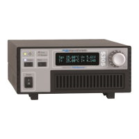
An overview of the TECSource's front panel design, buttons, and display functionality.
Explanation of the three control modes: T Mode, R Mode, and Ite Mode for temperature control.
Details on the different data sets that can be displayed on the TECSource's main screen.
Information on how measurements are displayed based on the selected control mode.
Configuration of core instrument parameters like Mount, Sensor, and Gain in the root menu.
Setting up the Proportional, Integral, and Derivative terms for precise temperature control.
Setting the Integral and Derivative terms for the PID control loop.
Configuring current, voltage, and temperature limits for output control and safety.
Setting the operating mode to T Mode, R Mode, or Ite Mode for temperature control.
Selecting the primary sensor to be used as the feedback sensor for the control loop.
Configuring Steinhart-Hart and RTD coefficients for various sensor types.
Setting high and low temperature limits for primary and auxiliary sensors.
Defining Tol Time and Tol Temp for evaluating temperature stability and control performance.
Configuring the function and voltage settings for the analog output.
Configuring the behavior of digital inputs and outputs.
Configuring digital outputs and controlling the electro-mechanical relay functions.
Configuring the built-in fan power supply and control modes.
Assigning functions to keys and setting communication parameters like baud rate.
Configuring parameters for operating the instrument in remote mode.
Adjusting system-wide settings like brightness, audible beep, and knob speed.
Configuring conditions that will cause the TEC output to turn off.
Listing conditions that trigger an output shutdown, configurable in the Out Off Menu.
Utilizing the AutoTune feature for automatic PID parameter calculation.
Configuration of advanced parameters like temperature rate and set point step.
Steps for installing the necessary USB drivers for computer communication.
Managing instrument settings by saving and restoring configurations.
Assigning and running scripts via function keys for automated instrument control.
Assigning and recalling saved instrument configurations using function keys.
Distinction between primary and auxiliary sensors and their roles in control and monitoring.
Wiring and configuration guidelines for auxiliary sensors.
Setting up digital inputs for interlock or remote control functions.
Configuring digital outputs for various instrument states like Stable or Limit.
Controlling the electro-mechanical relay for external device activation.
Using the dedicated interlock input to disable TEC output for safety.
Configuring the instrument for specific mounts to optimize settings and limits.
Defining Tol Time and Tol Temp for evaluating temperature stability and control performance.
Listing conditions that trigger an output shutdown, configurable in the Out Off Menu.
How sensor limits and output off settings affect instrument behavior.
Understanding thermistor operation, resistance vs. temperature, and Steinhart-Hart equation.
Understanding RTD operation, resistance vs. temperature, and IEC751 equations.
Comparing 2-wire and 4-wire measurement modes for RTDs to minimize measurement error.
Working with AD590 and LM335 IC sensors and their linear temperature correction formula.
Adjusting gain settings and tuning PID loop parameters for optimal control performance.
Understanding the PID formula and manually tuning parameters.
Performing AutoTune remotely via commands and monitoring its progress.
Setting the desired temperature ramp rate in degrees Celsius per minute.
Customizing the increment of the temperature set point for easier adjustment.
Configuring the TECSource for resistive heaters or heat/cool-only modes.
Conditions that must be met for the software-controlled voltage limit to engage.
Using the Cable R setting for software compensation of voltage loss.
Using 4-wire Kelvin connections for accurate remote TEC voltage measurements.
Configuring the analog output for direct voltage control, temperature error, or temperature.
Details on Analog Output modes for Temperature and ITE current proportionality.
Configuring the built-in fan power supply and control modes.
Applying user calibration to instrument functions using specific computer interface commands.
Ability to link the TECSource with a LaserSource for extended functionality.
Managing internal thermal load through tunable power supply and current limiting.
Graphical representation of safe operating current and voltage limits for the 5400-15-28 model.
Graphical representation of safe operating current and voltage limits for the 5400-30-28 model.
Graphical representation of safe operating current and voltage limits for the 5400-20-56 model.
Technical specifications for the current and voltage drive channels.
Specifications related to temperature range, resolution, and accuracy.
Specifications for current, voltage, and sensor measurement channels.
Detailed specifications for LM335, AD590, and RTD sensor measurements.
Specifications for power, dimensions, operating temperature, and interface type.
Error codes related to EEPROM corruption and communication issues.
Handling errors related to data format, configuration, and script execution.
Error codes indicating sensor open circuits or Peltier module faults.
Managing errors related to output limits, stability, and sensor changes.
Error codes for mode changes, AutoTune failures, and thermal trips.
Error codes related to user calibration resets and factory default resets.
Troubleshooting user errors, function key issues, and hardware faults.
Guidelines for instrument cleaning and replacing blown fuses.
How to obtain service, repair, and contact Arroyo Instruments for support.
Details on the product warranty, coverage period, and repair/replacement policy.
Exclusions from warranty coverage, including misuse and unauthorized modifications.
| Brand | Arroyo Instruments |
|---|---|
| Model | TECSource 5400 Series |
| Category | Temperature Controller |
| Language | English |