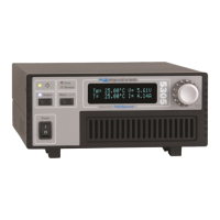
Page 28 · 5400 Series TECSource User’s Manual
Using the Auxiliary Interface
The Auxiliary Interface provides connections to the auxiliary sensors, the digital
inputs and output, an electromechanical relay, and an auxiliary +5V power
supply.
Auxiliary Sensors
Auxiliary sensors are wired for a common ground return, so take care to ensure
that a common ground will not cause interference with other parts of your
system. In addition, auxiliary sensors should be electrically isolated from all
other signal and power connections on the instrument.
Auxiliary sensor settings can be adjusted in the Aux Sensor Menu. The auxiliary
sensors share a common set of Steinhart-Hart coefficients for temperature
conversions which are independent from the primary sensors coefficients. This
allows for dissimilar sensor types to be used.
Each auxiliary sensor has a corresponding high and low temperature limit. By
default, auxiliary sensors that exceed their temperature limits will not cause the
output to shut down. If you want auxiliary sensors to cause temperature limit
shutdowns, set Out Off Menu » Apply Aux to Yes. See Working With Thermistors
below for more information on using thermistors.
Digital Inputs
The 5400 has two digital inputs: Digital Input 1 and Digital Input 2. They share a
common ground with the digital outputs and 5V auxiliary power supply. If left
unconnected, each digital input will be pulled up into an ‘On’ state via internal
pull-up resistors.
Each digital input can be assigned to act as either an additional interlock input,
or as a remote output on/off control. The logic of the digital input can be
reversed, or inverted, to allow for active low signals. These settings can be found
in the Digital I/O Menu » Di# Func and Di# Invert menu entries.
CAUTION
Connecting a sensor signal or sensor ground to any
other signal or power interface could cause damage to
your instrument. Sensors should be fully electrically
isolated from all other connections.