5400 Series TECSource User’s Manual · Page 9
Power and Cable Connections
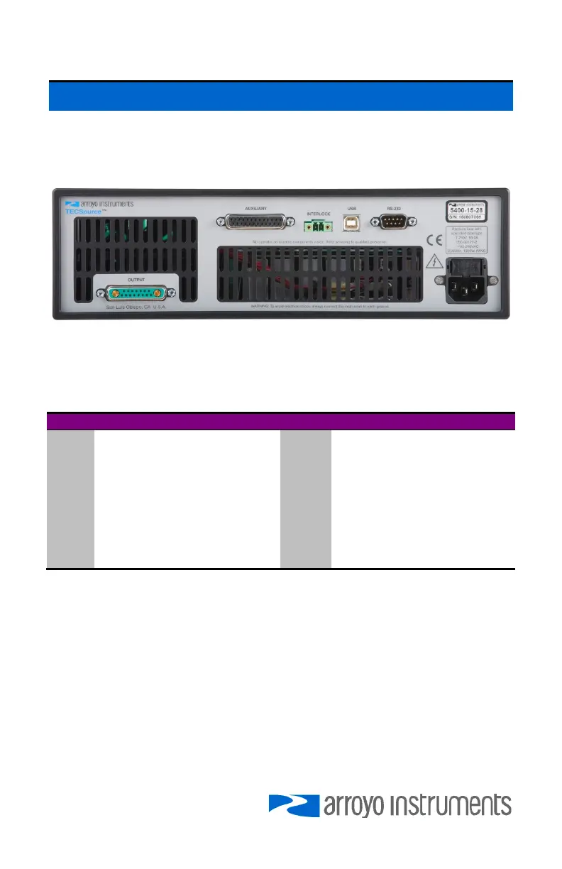
In addition to the input power connector described above, there are five
connectors on the rear panel of the TECSource: Output connector, Auxiliary
connector, Interlock connector, USB connector, and RS232 connector.
TECSource Rear Panel
TEC Output Connector
The Output connector is a female 17W2, and has the following pin-out:
Pin Description Pin Description
A1 TE (+) A2 TE (–)
1 TEC On LED+ 8 TEC On LED– (Signal Ground)
2 Remote TEC Voltage Sense+ 9 Remote TEC Voltage Sense–
3 Sensor 1– 10 Sensor 1 Remote Sense–
4 Sensor 1+ 11 Sensor 1 Remote Sense+
5 Sensor 3 (AD590) – 12 Sensor 3 (AD590)+
6 Sensor 2– 13 Earth Ground
7 Fan+ 14 Sensor 2+
15 Fan– (Signal Ground)
Output Connector (17W2 Female)
Inverting the TE Output
In the event the polarity of the TE pins is backwards, it is possible to reverse the
direction of the TEC current by setting the Advanced » Invert ITE to Yes. While
not recommended as it can lead to confusion when the controller is used later is
properly wired setups, this allows for correct operation of system when the TE
pins are wired backwards and rewiring is not possible or feasible.
Using Remote Sensor
The Remote Sensor 1 pins (10 & 11) are used in RTD 4-wire mode, and provide
a remote measurement of the RTD voltage to eliminate voltage measurement