AT32 Work Bench User Manual
2024.03.05 13 Ver 1.04
This window displays configurable interrupts for the current peripheral. When the corresponding
DMA channel is enabled, the corresponding DMA channel interrupt can be configured, for example,
the “USART1_IRQ” and “DAMA1_Channel3_2_IRQ” in Figure 12.
The “preemption priority” and “sub priority” are configured in the “NVIC Mode and configuration”
window. Refer to Section 4.2.6.
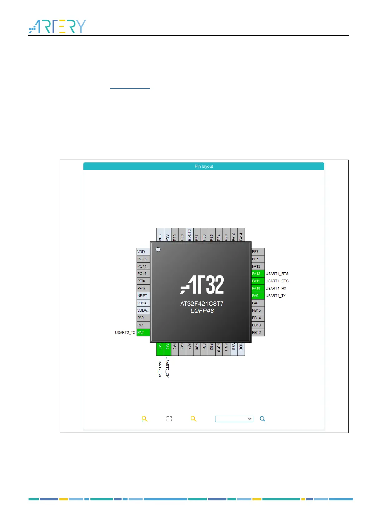
4.2.3 Pin layout
The pin layout of the selected package (such as LQFP48, QFN32 and TSSOP20) is displayed in
graphic. Each pin is represented by its name (such as PA9), configuration status, and current signal
distribution.
Figure 13. PIN layout