AT32 Work Bench User Manual
2024.03.05 19 Ver 1.04
Clock configuration
Users can configure the clock path and parameters in the Clock Configuration window, and use
drop-down menus and input boxes to modify the actual clock tree configuration to meet application
requirements.
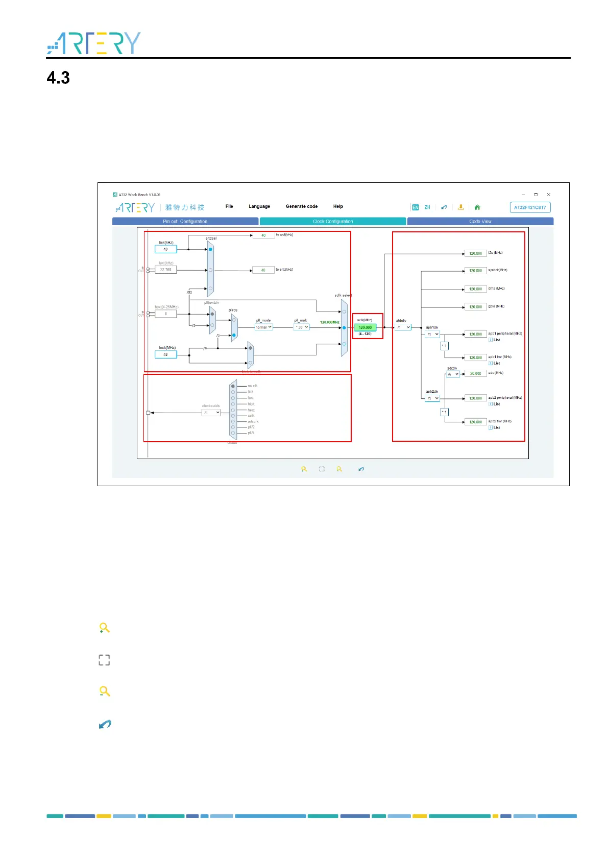
As shown in Figure 19, the Clock Configuration window mainly includes four blocks.
Figure 19. Clock configuration
1. Configuration: Select and configure the clock path and parameters as needed.
2. Output: Configure the clock output (CLKOUT).
3. SCLK: It is an input box when PLL is used as the system clock. Users can input the desired
system clock frequency to automatically configure the frequency multiplication factor.
4. Result: Display the clock frequency of the current peripheral, and peripherals on bus.
Users can press the Ctrl + scroll mouse wheel to adjust the MCU clock configuration window size.
The toolbar of the Clock Configuration window has the following functions:
: Zoom into the clock configuration view.
: Restore the clock configuration view to the initial size and position.
: Zoom out the clock configuration view.
: Reset clock configuration.
Note 1: Set the “LEXT” mode in the “CRM Mode and Configuration” window to enable LEXT.
Note 2: Set the “HEXT” mode in the “CRM Mode and Configuration” window to enable HEXT.
Note 3: Tick “Clock Output” in the “CRM Mode and Configuration” window to enable clockout.