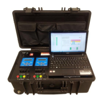
AMU Installation
11
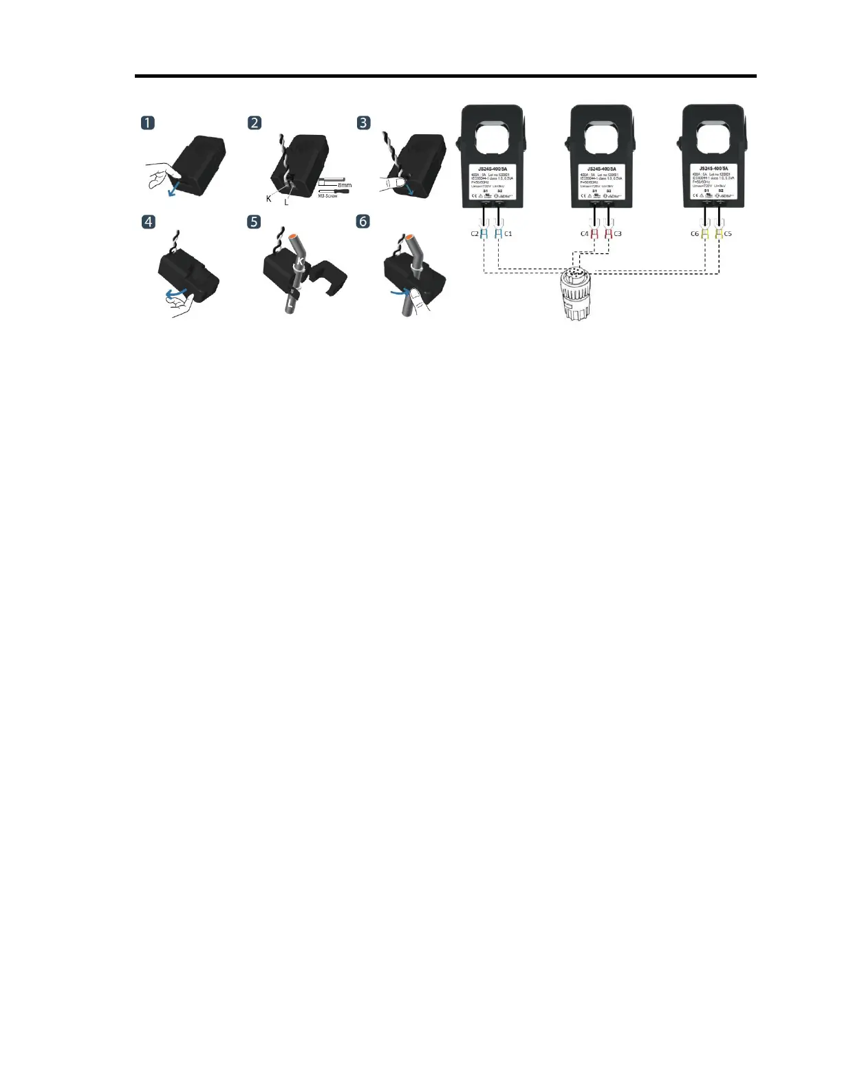
Connect C2 and C1 to S1 and S2 terminals of the first CT. Connect C4 and C3 to S1 and S2
terminals of the second CT. Connect C6 and C5 current cables to S1 and S2 terminals of the
third CT.
If the MCC has existing current transformers make direct connections to those current
transformers with 5 Amp secondary output.
If the nominal current is between 0 – 30 Amps and current transformers do not exist at the
measurement unit of the motor, use current transformers (NOT SUPPLIED) with appropriate
turn ratios. Turn ratios will be selected such that current inputs are between 1.5 – 5 Amps
for 5 Amp AMU and between 0.3 – 1 Amps for 1 Amp AMU.
3.2. Medium Voltage Motors: The test equipment has a limit of 480 volts for direct
connection. Therefore, testing on medium to high voltage motor and driven equipment
is performed by utilizing secondary circuit (low voltage) to access the currents and
voltages. Lethal voltages and currents are present at the input terminals of this
device. Accordingly, this unit must be used in accordance with all local and national
codes for the installation and operation of low voltage electrical equipment.
3.3. Inverter Driven Motors: Make sure that voltages are measured at the output terminals
of the inverter. Direct connections to the output terminals are made for low voltage
inverters. Voltage transformers (NOT SUPPLIED) are needed for medium voltage
inverters.
4. Turn the power switch of the AMT Toolkit and AMU unit on.
5. Ensure that AMU’s Power led is on.
6. Ensure that “IDLE” message appeared in the AMU’s LCD display. If the unit is not in IDLE
mode, press clear button until IDLE message appears in the LCD display.
7. Refer to section 3 for detailed information for the use of AMU unit.
Configuring AES for AMT Software
This section describes configuration of AMU unit using the “set up wizard”. Alternative
configuration is possible from the front panel by using the buttons of the AMU unit as
described in section 3.
1. Before configuring AES Configuration Application, ensure that motor is running and
voltage & current sockets are connected.