LIST OF FIGURES
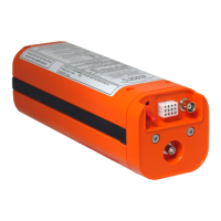
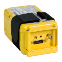
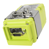
Figure 1 B406-4 ELT and Mounting Frame Assembly .......................................................................... 18
Figure 2 Remote Switch Panel Assembly Front View ........................................................................... 18
Figure 3 Buzzer ................................................................................................................................ 19
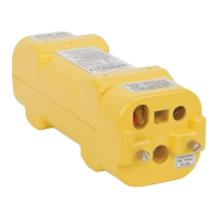
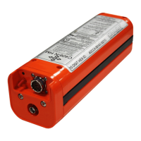
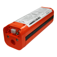
Figure 4 Battery Pack Assembly ........................................................................................................ 19
Figure 5 Antennas ............................................................................................................................ 20
Figure 6 ELT Operational Flow Diagram ............................................................................................. 21
Figure 7 ELT Orthogonal Axes ........................................................................................................... 30
Figure 8 Performance Testing Equipment Setup ................................................................................. 31
Figure 9 Current Draw Test Setup ..................................................................................................... 33
Figure 10 Short and Long 406 MHz Message Examples ....................................................................... 34
Figure 11 ELT Removal Sequence ..................................................................................................... 39
Figure 12 Battery Pack Removal ........................................................................................................ 40
Figure 13 B406-4 ELT Outline and Dimensions ................................................................................... 44
Figure 14 Typical Mounting Tray Installation ...................................................................................... 45
Figure 15 Rod Antenna 110-320 and Blade Antenna 110-328-01 Outlines and Dimensions ................... 47
Figure 16 Blade Antennas 110-333 and 110-337 Outlines and Dimensions ........................................... 48
Figure 17 Blade Antenna 110-337-11 Outline and Dimensions ............................................................ 49
Figure 18 Remote Switch Panel Assembly Outline and Dimensions ...................................................... 50
Figure 19 Buzzer Outline and Dimensions .......................................................................................... 51
Figure 20 Remote Switch Panel Harness Wiring Diagram .................................................................... 53
Figure 21 Remote Switch Panel Harness Wiring at ELT End ................................................................ 56
Figure 22 ELT Installation Sequence .................................................................................................. 58
Figure 23 Battery Pack Installation .................................................................................................... 60
Figure 24 Battery Pack Retaining Screw Tightening Pattern ................................................................ 61
Figure 25 B406-4 ELT Main Assembly and Installation ........................................................................ 67
Figure 26 Electrical Components ....................................................................................................... 69
Figure 27 Antennas .......................................................................................................................... 70