14 | 7030 Mobility Controller Aruba 7030 Mobility Controller | Installation Guide
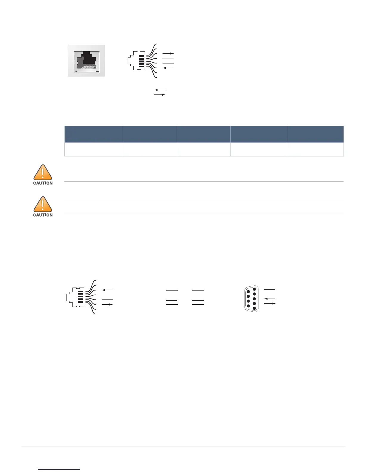
Figure 5 Serial Console Port Pin-Out
The communication settings for the Console port is shown in the following table:
Serial Console Port Adapter
A modular adapter can be used to convert the female RJ-45 connector to a male DB9 connector. See Figure
6 for complete details.
Figure 6 RJ-45 (Female) to DB9 (Male) Modular Adapter Conversion
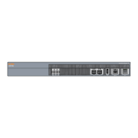
Power Supply
The Aruba 7030 controller is equipped with an integrated AC power supply of 80W.
Grounding Point
To meet safety and electromagnetic interference (EMI) requirements and to ensure proper operation, the
controller must be adequately grounded before power is connected. Connect a grounding cable to earth
ground and then attach it to the chassis grounding point using two screws.
Comply with electrical grounding standards during all phases of installation and operation of the product.
Do not allow the controller’s chassis, network ports, power supply, or mounting brackets to contact any
device, cable, object, or person attached to a different electrical ground. Also, never connect the device to
external storm grounding sources
Table 8 Console Terminal Settings
Baud Rate Data Bits Parity Stop Bits Flow Control
9600 8 None 1 None
Serial
Console Port
1
2
3
4
5
6
7
8
TxD
GND
RxD
RJ-45 Female
Pin-Out
Direction
Input
Output
GND
The CONSOLE port is compatible only with RS-232 devices. Non-RS-232 devices, such as APs, are not supported.
Do not connect the Console port to an Ethernet switch or a PoE power source. This may damage the controller.
3
4
5
2
5
63
RJ-45 DB-9
Internal
Connections
TxD
GND
RxD
1
2
3
4
5
6
7
8
TxD
GND
RxD
RJ-45 Female
Pin-Out
DB-9 Male
Pin-Out
TxD
RxD
Ground
5
4
3
2
1
9
8
7
6