Aruba AP-85 Outdoor Access Point Series | Installation Guide AP-85 Series Hardware Overview | 11
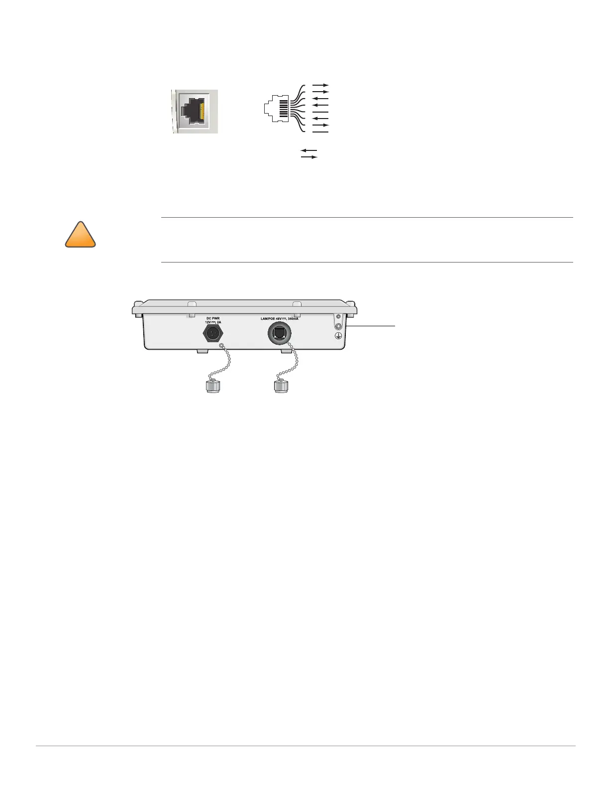
Figure 4 10/100Base-T Fast Ethernet (RJ-45) Port Pin-Out
z Grounding Point
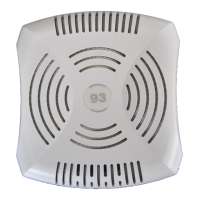
Figure 5 AP-85TX Bottom View
AP-85FX/LX Bottom View
The bottom of the AP-85FX/LX unit (see Figure 5) has the following ports and connections:
z DC PWR 12 VDC, 2 A: The AP can accept DC power in the range of 8 to 16 VDC. If the AP-85FX/LX is not connected to an
AC power source, the AP must be powered by a DC power source. An outdoor rated, two-wire, 8-foot long DC power
cable (wiring harness) is supplied with the unit. For proper installation instructions, see "DC and AC Power Cables" on
page30.
z LAN - OPTICAL:
AP-85FX: This model has a 100BASE-FX data uplink port for multi-mode, dual-fiber network connectivity. A multi-
mode, fiber patch cable with a duplex LC connector is required for use. The cable is not included and must be
purchased separately.
AP-85LX: This model has a 100BASE-LX data uplink port for single-mode, dual-fiber network connectivity. A single-
mode, fiber patch cable with a duplex LC connector is required for use. The cable is not included and must be
purchased separately.
z CONSOLE: A serial console port is provided for connection to a terminal, allowing direct local management.
It is important that the AP-85TX be properly grounded and a grounding point is provided on the
bottom of the AP-85TX model. A professional installer should ensure that grounding is available and
meets applicable local and national electrical codes.
AP-85
10/100Base-T
Fast Ethernet (RJ-45)
RJ-45 Female
Pin-Out
*POE optional
**Serial optional
Serial RxD**
Serial RGND** (POE positive*)
Serial TxD**
Serial TGND** (POE negative*)
1
2
3
4
5
6
7
8
ETH Tx+ (POE negative*)
ETH Tx– (POE negative*)
ETH Rx+ (POE positive*)
ETH Rx– (POE positive*)
Direction
Input
Output