21
PRESSURE SWITCH ADJUSTMENT
1 - Connect the Sentronic connector according to page 13
Do not apply pressure to the input port.
2 - Turn P6 potentiometer clockwise to the maximum.
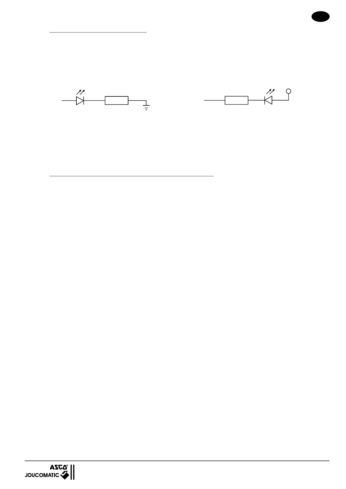
3 - Connect a LED with resistor 4,7 KΩ between pin M and pin B or pin M and pin A according to
the pressure switch option.
4 - Apply a set point according to the half window size (without pressure at the input of the valve)
Example : for a 0-3 bar SENTRONIC you need a ± 70 mbar window size.
0,07 : 3 = 2,3 % of 10 volts. Apply a set point of 0,23 V.
5 - Turn P6 counter clockwise until the output changes (LED from on to off).
OPTION : EXTERNAL FEEDBACK VALUE INPUT (consult us)
Instead of the internal pressure sensor, an external sensor for pressure, force, speed, position, etc. . .
is used. The external feedback value is supplied to pin 6 of the connector.
Voltage input 0 . . . 10 V : 100 kΩ input resistance
Current input 0 . . . 20 mA : 500 Ω shunt resistance
Current input 4 . . . 20 mA : 500 Ω shunt resistance
The span and zero point must be adjusted as shown on page 19
PNP
(0V)
B
M
(+ 24V)
4,7 kΩ
NPN
(0V)
A
M
(+ 24V)
4,7 kΩ
 Loading...