15
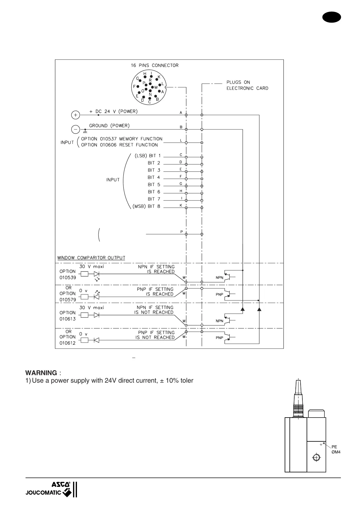
I = 500 mA maxi
I = 500 mA maxi
I = 500 mA maxi
I = 500 mA maxi
Output
or
Input
*
PRESSURE FEEDBACK
0 - 10 V (option 0 - 20mA ou 4 - 20mA)
WIRING CONNECTOR
ON SENTRONIC WITH DIGITAL CONTROL
G 1/8 (Ø 3 mm) - G 1/4 (Ø 6 mm) - G 1/2 (Ø 12 mm) - G1 (Ø 20 mm)
with memory function 010 537
with zero switch 010 606
;;;;;;;
;;;;;;;
;;;;;;;
;;;;;;;
WARNING :
1) Use a power supply with 24V direct current, ± 10% tolerance with a max. 10% ripple
(no supply per diode bridge). Over voltage or a ripple rate above 10% can damage the
electronic.
2) Max current of pin M is 500 mA (output NPN/PNP). Pin M has a short circuit and a
overload protection.
3) If you connect a relay (inductive load) to pressure switch output, you must use a
freewheel diode or a varistor to avoid voltage peaks.
4) Don't connect to unused pins on the female connector.
5) In case of an interruption in the pressure supply, shut off the power supply (+24V) or
switch the set point to zero to avoid excessive heating of the coil.
6) Grounding for personal protection must be done at the PE-thread (ØM4) on the body.
7) Use a shielded cable for EMC-protection.
Connect the shield to ground and to the connector body.
View on the soldered
wires side of female
connector
*
External feedback value input if the valve is configurated for external sensor
 Loading...