Ascon Tecnologic - KX6 - ENGINEERING MANUAL - PAG. 2
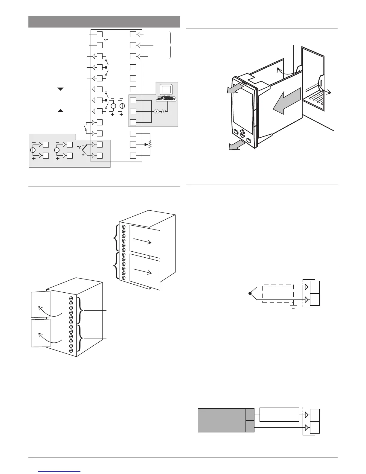
2 CONNECTION DIAGRAM
Thermocouple
DI1
Out1 (2A)
Out2 (2A)
Out3 (2A)
Out4 (2A)
Analogue Input
RS485
mA
Neutral
100... 240 VAC
100... 240 VAC
24 VAC/VDC
C
NO
NO
C
Phase
1
2
V/mV
1
2
2
1
4
3
6
5
8
7
10
9
12
11
NO
14
13
16
15
18
17
20
19
22
21
24
23
NO
C
IN1
IN2
GND
D-
D+
DI2
Potentiometer
100Ω... 10 kΩ
mA (600Ω max.)
V (500Ω max.)
2.1 Terminal covers
The controller terminals are protected with plastic covers. In
order to make the connections, move the covers as shown in
the illustrations.
Te rminals
1... 6
Te rminals
7... 12
Te rminals
19... 24
Te rminals
9... 24
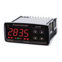
2.2 Controller unplugging
The controller can be extracted from its housing (without
removing the cabling).
1A
2
1A
1
1
2 Extract the controller
module from the
external housing
1, 1A Pulling the controller from the upper
and lower sides, carefully open
in sequence the 2 retainers
To re-insert the controller in its housing, reverse the
extraction procedure.
2.3 General notes about wiring
1. Do not run input wires together with power cables.
2. External components (like zener barriers, etc.) connected
between sensor and input terminals may cause errors in
measurement due to excessive and/or not balanced line
resistance or possible leakage currents.
3. When a shielded cable is used, it should be connected at
one point only.
4. Pay attention to the line resistance; a high line resistance
may cause measurement errors.
2.4 Inputs
2.4.1 Thermocouple Input
1
2
+
_
Continuity detection current: 250 nA.
Cold junction: automatic compensation between 0... 50°C.
Cold junction thermal drift: 0.1°C/°C after a warm-up of
20 minutes.
Input impedance: > 1 MΩ.
Calibration: According to EN 60584-1.
Note: For TC wiring use proper compensating cable
preferable shielded.
2.4.2 mA Input
0/4... 20 mA input wiring for passive transmitter
using an external pws
+
_
+
_
1
2
0/4...20 mA
Passive
transmitter
_
External
PWS
+
Input impedance: < 50 Ω.