Tip Selection
14 311139B
Uni-Tip Selection Chart
Example: For an 8 in. (203 mm) fan width and 0.013 (0.33 mm) hole
size, order Part No. 69-413.
Choosing the Correct Tip for the
Job
Consider the coating and surface to be sprayed. Make
sure you use the best tip hole size for that coating and
the best fan width for that surface.
Tip Hole Size
Tip hole size controls the flow rate - the amount of paint
that comes out of the gun.
HINTS:
• Use larger tip hole sizes with thicker coatings and
smaller tip hole sizes with thinner coatings.
• Maximum tip hole sizes supported by the sprayer:
– ESP: 0.015 in. (0.38 mm)
– 1500: 0.015 in. (0.38 mm)
– 1700: 0.017 in. (0.43 mm)
– 1900: 0.019 in. (0.48 mm)
• Tips wear with use and need periodic replacement.
Fan Width
Fan width is the size of the spray pattern, which deter-
mines the area covered with each stroke. For a given tip
hole size, narrower fans deliver a thicker coat, and wider
fans deliver a thinner coat.
HINTS:
• Select a fan width best suited to the surface being
sprayed.
• Wider fans allow for faster coverage on broad,
open surfaces.
• Narrower fans allow for better control on small,
confined surfaces.
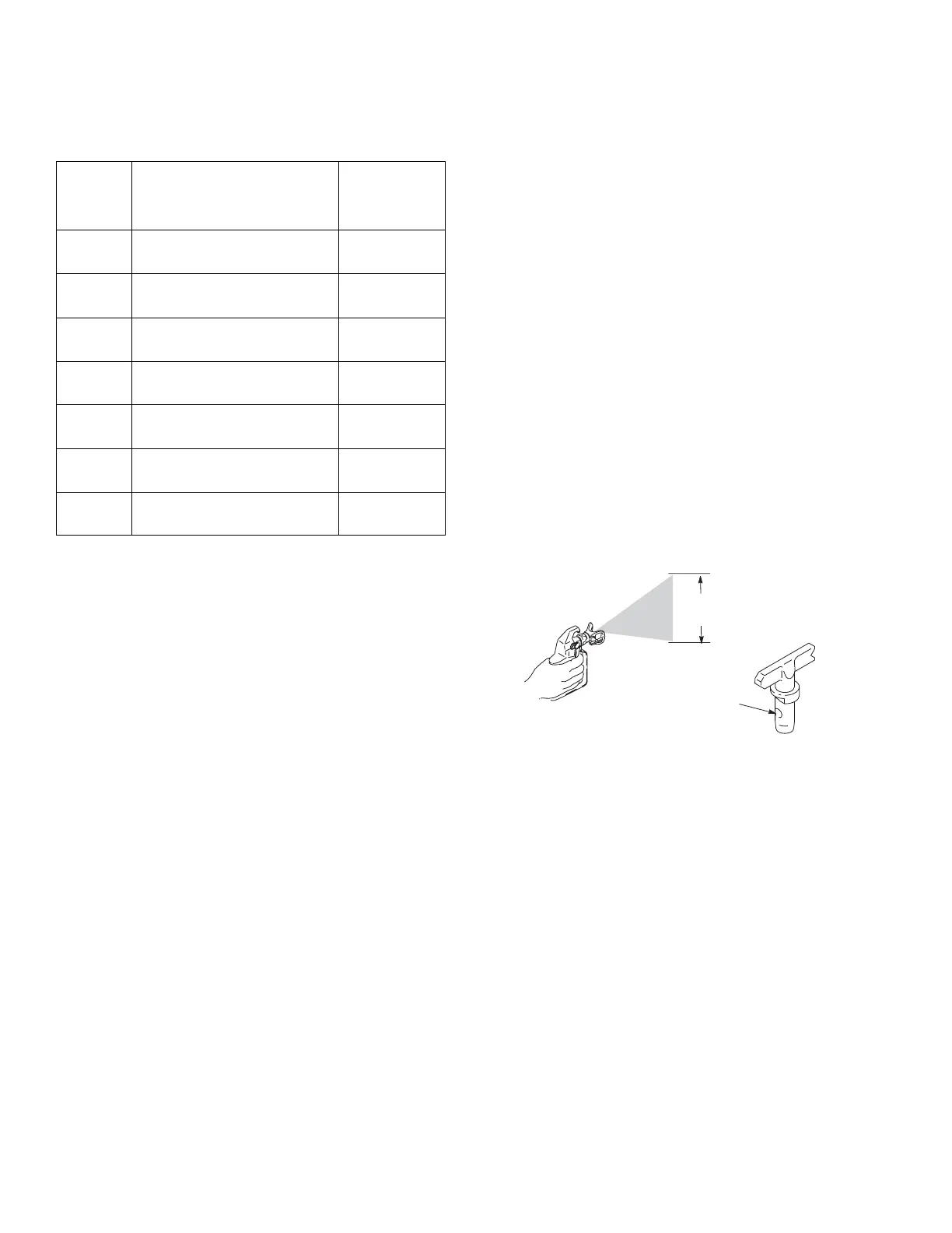
Understanding Tip Number
The last three digits of the tip number (example: 69-413)
contain information about the hole size and about the
fan width on the surface when the gun is held 12 in.
(30.5 cm) from the surface being sprayed.
Tip
Part
No.
Fan Width 12 in.
(305 mm) from surface Hole Size
69-411 8 in. (203 mm) 0.011 in.
(0.28 mm)
69-413 8 in. (203 mm) 0.013 in.
(0.33 mm)
69-415 8 in. (203 mm) 0.015 in.
(0.38 mm)
69-515 10 in. (254 mm) 0.015 in.
(0.43 mm)
69-417 8 in. (203 mm) 0.017 in.
(0.43 mm)
69-517 10 in. (254 mm) 0.017 in.
(0.43 mm)
69-519 10 in. (254 mm) 0.019 in.
(0.48 mm)
)LUVWGLJLWZKHQGRXEOHG
DSSUR[LPDWH
IDQZLGWK
/DVWWZRGLJLWV WLSKROHVL]HLQWKRXVDQGVRIDQLQFK
WLSKDVD
LQKROHVL]H
WLSKDVWRLQ
IDQZLGWK
WLD