Do you have a question about the Assa Abloy Abloy EL590 and is the answer not in the manual?
Details mechanical and electrical functions that can be selected for the lock case.
Explains the monitoring capabilities of the lock case, such as bolt deadlocked status.
Procedures to verify the lock's functionality and sensitivity after installation per EN 179.
Procedures to verify the panic exit device's functionality and sensitivity per EN 1125.
Instructions for fitting the manipulation protection cover and cable cover.
Guides on how to alter the opening direction of the trigger bolt and latch bolt.
Steps to modify the bolt throw between 20 mm and 14 mm.
Instructions for adjusting the delay settings of the lock case using a Torx screw.
Steps to switch the handle function between mechanical and electrical control.
Guide for installing the monitoring switch for cylinder or thumbturn.
Procedures for lock maintenance and disconnecting the cable plug.
Diagram and explanation of wiring for control lines and signal inputs.
Details on connecting potential-free relay outputs for lock status indications.
Wiring instructions for micro switches indicating cylinder or handle status.
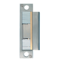
Provides specific drilling dimensions for LP712, LP722, and LP732 strike plates.
Shows the recommended space for routing electrical wires during installation.
Guidance on preserving the fire door's original structure during lock installation.
Specific figures illustrating lock case and cable installation for fire doors.
| Operating voltage | 12-24 V DC |
|---|---|
| Bolt Throw | 20 mm |
| Operating Temperature | -20°C to +60°C |
| Material | Stainless steel |
| IP Rating | IP54 |
| Keypad | No |
| Bluetooth | No |
| Monitored functions | Bolt position |
| Suitable for | Fire doors |
| Battery Life | Not applicable |
| Compatibility | Access control systems |