Do you have a question about the Assa Abloy PASSPORT 1000 and is the answer not in the manual?
Details FCC regulations for device operation and potential interference.
Outlines Industry Canada requirements and operating conditions.
Basic precautions to prevent damage from electrostatic discharge to components.
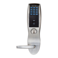
Overview of the Passport 1000 P2 Mortise lock, its features, and benefits.
Lists the lock's physical components, materials, and compliance standards.
Details WiFi, scheduling, encryption, user capacity, and audit trail capabilities.
Lists UL/CUL certifications and specific UL 294 access control ratings.
Specifies battery types and optional hard power input requirements.
Lists various part numbers for outside escutcheons with different reader options.
Includes part numbers for mounting plate, controller, and inside escutcheon assemblies.
Lists the essential tools needed for the installation process.
Details parts related to the cylinder, rosette, and cylinder rosette.
Lists various lock body configurations and trim pack options.
Identifies spindle springs and the mortise screw pack for assembly.
Lists additional tools needed for the installation, including security allen wrench.
Guidance on verifying door hand and applying templates for proper lock installation.
Instructions for adjusting the lock body's hand orientation.
Steps for reversing the latchbolt to match the door's handedness.
Procedure for inserting the lock body into the door mortise and securing it with screws.
Steps for inserting, orienting, and securing the outside cylinder into the door.
Verifies the correct operation of the cylinder after installation.
Steps for attaching the outside lever and ensuring proper spindle engagement.
Procedure for attaching the inside rose and lever to the spindle.
Instructions for inserting, orienting, and securing the thumb turn for deadbolt functions.
Steps for applying the optional gasket and mounting the outside escutcheon.
Steps for positioning, routing wires, securing the plate, and ensuring UL compliance.
Instructions for connecting the 10-pin lock body and 24-pin reader connectors.
Procedure to secure the reader and mounting plate to the door using through-bolts.
Steps for inserting and securing the controller onto the mounting plate.
Procedures for initial battery installation and guidelines for battery replacement.
Steps for positioning and securing the inside escutcheon, ensuring wire clearance.
Steps for attaching the outside front plate using flat head screws.
Tests to verify correct operation of the inside lever, cylinder, and deadbolt.
Checks LED indicators for status and low power conditions, and battery voltage.
Ensures latchbolt and deadbolt extend fully into the strike plate without binding when closing the door.
| Brand | Assa Abloy |
|---|---|
| Model | PASSPORT 1000 |
| Category | Locks |
| Language | English |