80-9352-0020-020 Rev 2 06/23
Copyright © 2023, ASSA ABLOY Accessories and Door Controls Group, Inc. All rights reserved. Reproduction in whole or in
part without the express written permission of ASSA ABLOY Accessories and Door Controls Group, Inc. is prohibited.
5
5200 Series (PUSH Side) Power Operator
80-9310-0610-999 Rev 1
When door swings
away from you, mount
closer body with this
label facing you.
THIS SIDE OUT
PUSH SIDE
NortonRixson.com
Door
80-9310-0610-999 Rev 1
When door swings away
from you, mount closer
body with this label
facing you.
THIS SIDE OUT
PUSH SIDE
NortonRixson.com
Door
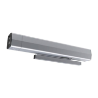
D. Install the operator body assembly.
1. Using the four (4) screws provided, install
the operator body to the backplate.
(Figure 8)
NOTES:
y Tighten screws in a cross pattern until
all four (4) screws are tight. (Figure 8)
y The operator body is properly orientated
for PUSH SIDE application when:
– The motor is toward the hinge side
of the door.
– The monitor board is facing away
from the backplate.
– “This side out PUSH SIDE” label is
facing away from the backplate.
(Figure 8)
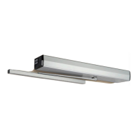
2. Using the supplied cable management
clip, secure the cables along operator body.
(Figure 9)
1
4
2
3
Figure 7
Figure 8
Left Hand Shown
C. Install the end caps.
1. Install two (2) screws on each end of
backplate, leaving an approximate 3/16"
gap between the head of the screw and the
backplate. (Figure 7)
2. Slide the end caps behind the screw heads
and tighten both screws. (Figure 7)
NOTE: The end cap with the 3-position
switch is always located on the conduit hole
side of backplate.
Switch End Cap
End Cap Screws
Conduit Hole
Figure 9
Monitor
Board
 Loading...