V4.4 03/08/18 TD0036 Page 6 of 39
This Document is uncontrolled when printed unless over stamped “CONTROLLED DOCUMENT”
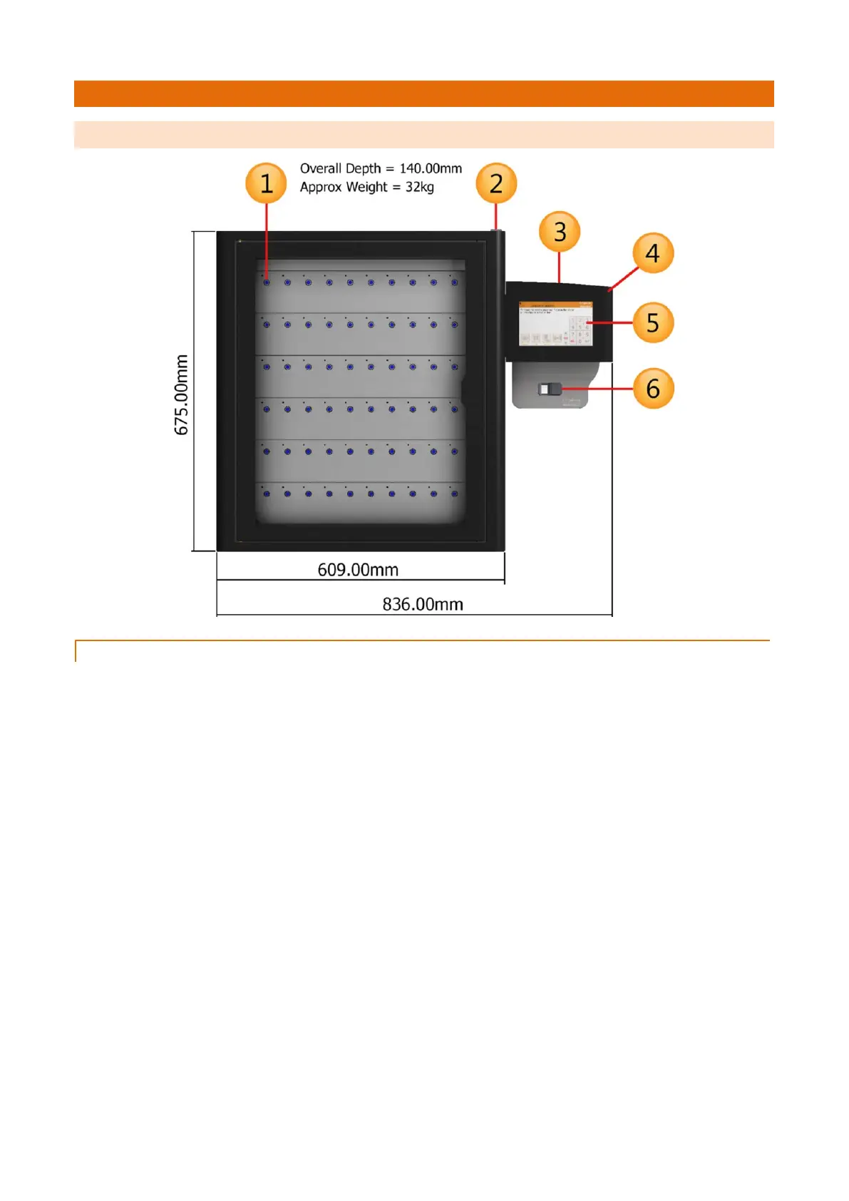
3. SYSTEM & IFOB DIAGRAM
3.1 SYSTEM DIAGRAM
3.1.1 SYSTEM KEY
1. Receptor Slot
The Receptor Slot holds the iFob in place.
2. Manual Door Release Cam Lock
2 master keys are supplied with your Traka system. The master key can be used for gaining access to the keys in
the system in an emergency situation. It can also be used during servicing and maintenance. We ask that you do
not keep the master keys in the Traka cabinet.
3. Pod Cam Lock
As well as the manual door release, the master key can also be used for gaining access to the system electronics
during servicing and maintenance.
4. Control Pod
Incorporates the touch screen, reader (if applicable) as well as the cam Lock providing access to the systems
electronics.
5. Touch Screen
The Touch sensitive LCD works as a user friendly interface for our embedded application. The numeric keypad,
alphabetic keyboard and receptor buttons are incorporated into this easy to use 7” LCD.
6. Card /Proximity Reader
Traka supports a wide array of access devices. The primary job of any access device is to identify the user to the
Traka system. Once the system knows who you are, it can grant or deny access to specific keys accordingly.
 Loading...