V4.4 03/08/18 TD0036 Page 8 of 39
This Document is uncontrolled when printed unless over stamped “CONTROLLED DOCUMENT”
4. EXTENSION SYSTEMS OVERVIEW
If your system does not have extension cabinets you can skip this section.
Additional ‘extension’ systems are installed alongside the main system. Up to three additional extensions can be added
for a total of four systems.
NOTE: Each extension cabinet will be clearly marked to indicate which order they should be located next
to the main system. It is important that the cabinets are located in this order as all DIP switch address
configuration and position numbering will already have been carried out at Traka during test.
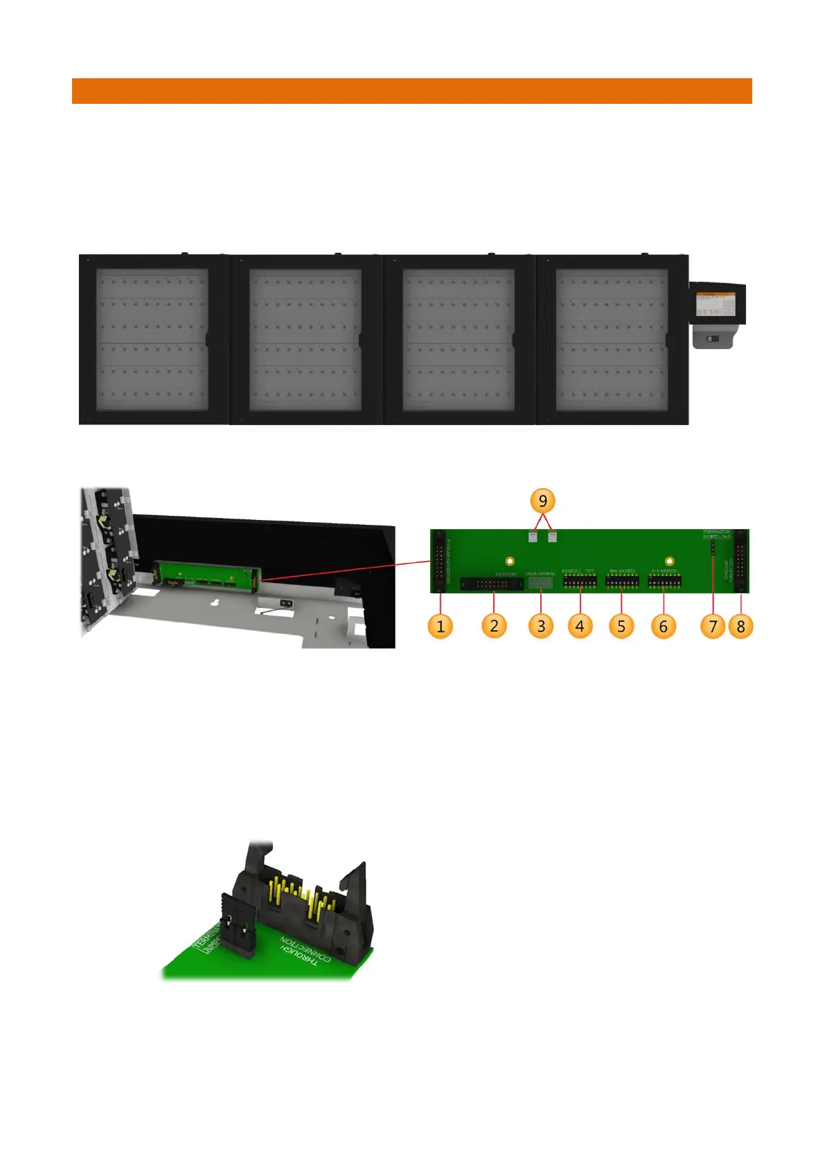
Each system will be linked together via a receptor cable that connects to the CAN Interface PCB. The CAN Interface
PCB is secured inside the top of each cabinet.
1. Primary CANbus – through-connection connects to the next extension cabinet in the chain.
2. Secondary CANbus – connects to the receptor strips in the local cabinet.
3. Cabinet Door Solenoid and Switch – connects to the door lock mechanism in the local cabinet. A door
lock extension cable is provided for extension cabinets.
4. Cabinet Address – (0=Off, 1=On) 0000 = Cabinet 1, 1000 = Cabinet 2, 0100 = Cabinet 3, 1100 =
Cabinet 4.
5. Max Receptor Address – must be set to match the bottom (highest address) receptor strip in the local
cabinet.
6. Min Receptor Address – must be set to match the top (lowest address) receptor strip in the local
cabinet.
7. Termination Jumper Links – must be fitted here on the last cabinet in the chain only as show below.
8. Primary CANbus – through-connection connects to the Traka Touch PCB (if it is in the main cabinet) or
the previous extension cabinet (if it is in an extension system).
9. TMPR1 – Connection for the Tamper Switch on the receptor frame (V3.2 and above PCB only).
TMPR 2 – Connection for the Tamper Switch on the rear of the cabinet (V3.2 and above PCB only).
 Loading...