12
ENGLISH
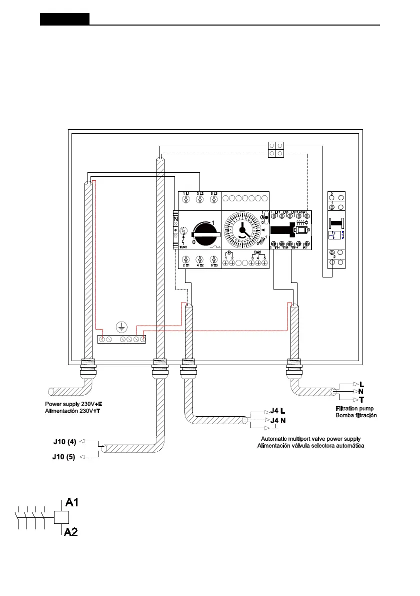
2.2 EXAMPLE OF CONNECTING A SINGLE PHASE 230 V ELECTRICAL CABINET
Before proceeding with the installation of the materials, users must ensure that the assembly and
maintenance work is carried out by qualifi ed and authorised workers who have read and unders-
tood the installation and service instructions.
The following diagram shows the external connections required to connect a System VRAC multi-
port valve to an ASTRALPOOL 25717 cabinet.
Disconnect the A1 end of the cable leading from connection 2 of the 3-position switch and add a
terminal block for the valve connection.
A1 / A2 are the terminals used to connect the fi ltration pump's contactor coil. Terminal
J10 of the multiport valve must always be connected to connection A1 of the contactor
coil.
It is important to ensure that nothing is connected in parallel with the solenoid valve of
the pump contactor and that the total power consumption does not exceed 0.4 A.
In cases where another component has to be connected which needs be activated
at the same time as the pump, we recommend the use of an auxiliary contact of the
pump contactor.