17
ENGLISH
5. DISASSEMBLY PROCEDURE
5.1 Valve disassembly procedure:
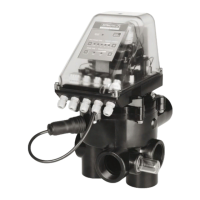
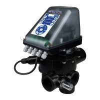
The automatic valve consists of two sections, the hydraulic part which includes a conventional
valve and an automatic module.
The fi lter valve is disassembled in the same manner as a manual valve.
5.2 How to disassemble the electronic module:
(illustrations in APPENDIX 1) BEFORE ANY OPERATION IS CARRIED OUT ON THE VALVE, IT
MUST DISCONNECTED FROM THE POWER SUPPLY.
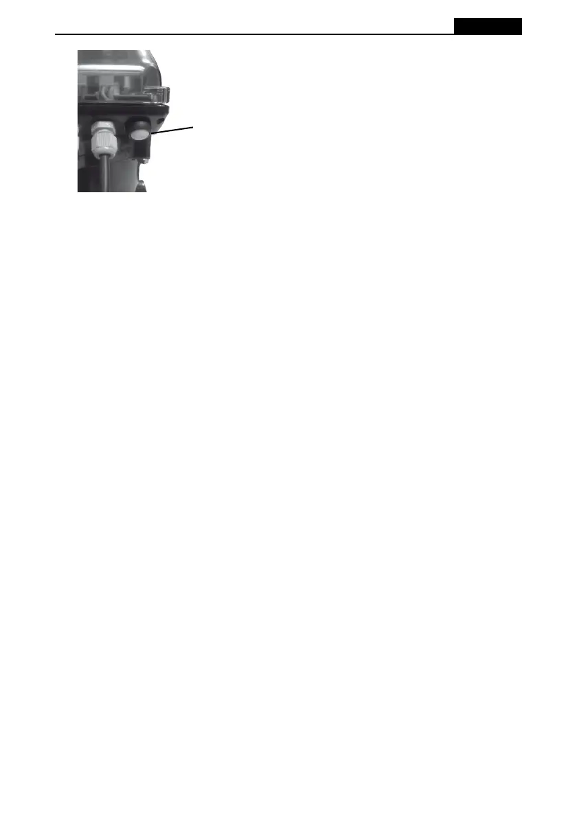
Disassembly: First remove the four screws which hold the cover (1) in place. (Fig. 2).
Disconnect all input wires to the module (AAPPENDIX 1 - Fig. 8). WARNING: All mains power
supply connections must be removed fi rst.
Refi t the cover 1 (Fig. 2)
Remove the three screws (11) which hold the module in place on the valve (Fig. 3).
Carefully remove the module in an upwards direction.
Protect inside suitable packaging to prevent any damage and send it to the manufacturer.
From this point there are two possibilities:
1. Replacement of the module.
2. Temporarily convert the system to manual valve operation.
5.3 Instructions for installing the module on the valve.
The manufacturer will ship the valve-module assembly to the technical service or installer ready for
installation. It should be installed as follows:
1. Install the valve assembly by positioning the module so that marking 2 (APPENDIX 1 - Fig. 3)
coincides with the mark on the valve cover, carefully lower the module until it is correctly in
place with respect to the screw 3 (APPENDIX 1 - Fig. 4). In a situation where it does not fi t, the
screw may be rotated until it couples with the motor pin (4) (APPENDIX 1 - Fig.4). Care must
be taken not to lower it too brusquely since this could damage the module’s microswitches.
2. Install the three screws (11) (APPENDIX 1 - Fig. 3 ).
3. Remove the cover 1 (APPENDIX 1 - Fig. 2) by removing the four screws (13) in order to access
the connection strip.
4. Connection (MAKE SURE THERE IS NO MAINS VOLTAGE). Connect the cables as indicated
in the attached diagram. IMPORTANT! Use the gland seals that come installed in the module.
5. Replace the cover 1 (APPENDIX 1 - Fig. 2) and replace it with the screws (13).
6. Connect the power input to the control board. The valve will be in the Filtration position, standing
by for when the programmed time is entered.