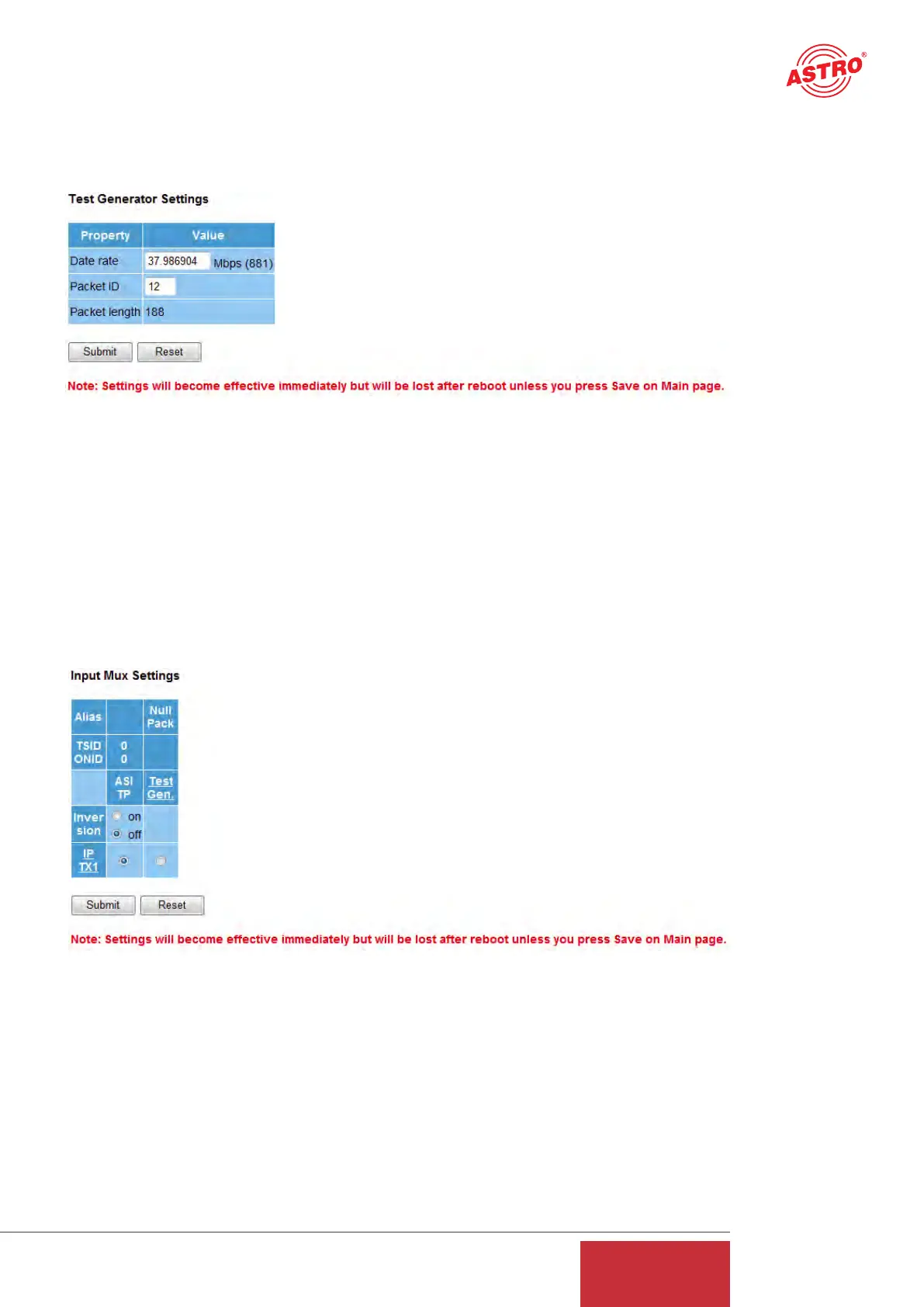
6 Test generator
Clicking on the "Test Gen" submenu takes you to the test generator settings. This internal test
generator is able to produce a test signal in order to perform a connection test, for example, and
to test this connection using a data stream.
Figure 7: Configuring the test generator
The generated data stream comprises zero packets with a length of 188 and can be configured in
a range from 1 - 197 Mbps. If the system contains several U 261 Gateways, a packet ID can be
allocated to distinguish the test signals.
7 Configuring the input multiplexer
Clicking on the "Input Mux" submenu takes you to the input multiplexer settings. The input or out-
put multiplexer is always seen from the ASI signal when the multiplexers are named. The U 261
has an ASI input which can be used to convert an ASI signal into IP signals.
Figure 8: Configuring the input multiplexer
This ASI signal is supplied via the BNC socket on the front and can be inverted prior to conver-
sion into IP (inversion on/off). In addition, there is the option of using the signal from the test gene-
rator (see chapter 6) and of converting it into an IP signal. The configuration of this IP transmitted
signal is explained in chapter 9.
11
User Guide
U 261