IPIBL-LA(Berkeley-GL8E)14
2. ATX power connectors (24-pin ATXPWR, 4-pin ATX12V)
TheseconnectorsareforanATXpowersupply.Theplugsfromthepower
supplyaredesignedtottheseconnectorsinonlyoneorientation.Findthe
properorientationandpushdownrmlyuntiltheconnectorscompletelyt.
• Donotforgettoconnectthe4-pinATX+12Vpowerplug;otherwise,the
systemwillnotbootup.
• MakesurethatyourATX12Vpowersupplycanprovide8Aonthe+12V
leadandatleast1Aonthe+5-voltstandbylead(+5VSB).Theminimu
recommendedwattageis230W,or300Wforafullyconguredsystem.The
systemcanbecomeunstableandmightexperiencedifcultypoweringupif
thepowersupplyisinadequate.
• YoumustinstallaPSUwithahigherpowerratingifyouintendtoinstall
additional devices.
6.2 Internal connectors
Thissectiondescribesandillustratestheinternalconnectorsonthemotherboard.
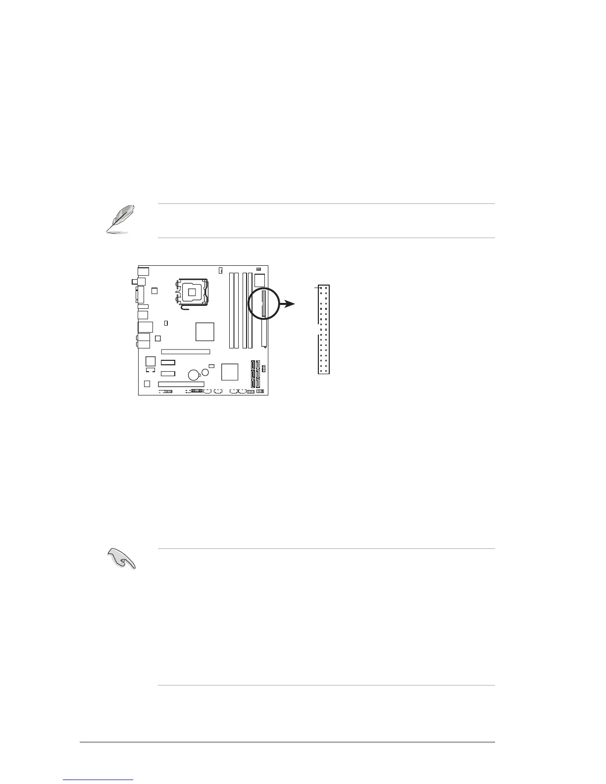
1. Floppy disk drive
connector (34-1 pin FLOPPY)
Thisconnectorisfortheprovidedoppydiskdrive(FDD)signalcable.Insert
one end of the cable to this connector, then connect the other end to the
signalconnectoratthebackoftheoppydiskdrive.
Pin 5 on the connector is removed to prevent incorrect cable connection when
usinganFDDcablewithacoveredPin5.
IPIBL-LA
NOTE: Orient the red markings on
the floppy ribbon cable to PIN 1.
IPIBL-LA(Berkeley-GL8E)
Floppy disk drive connector
FLOPPY
PIN 1