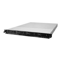
ASUS RS500-E8 Series
4-3
Internal connectors
Page
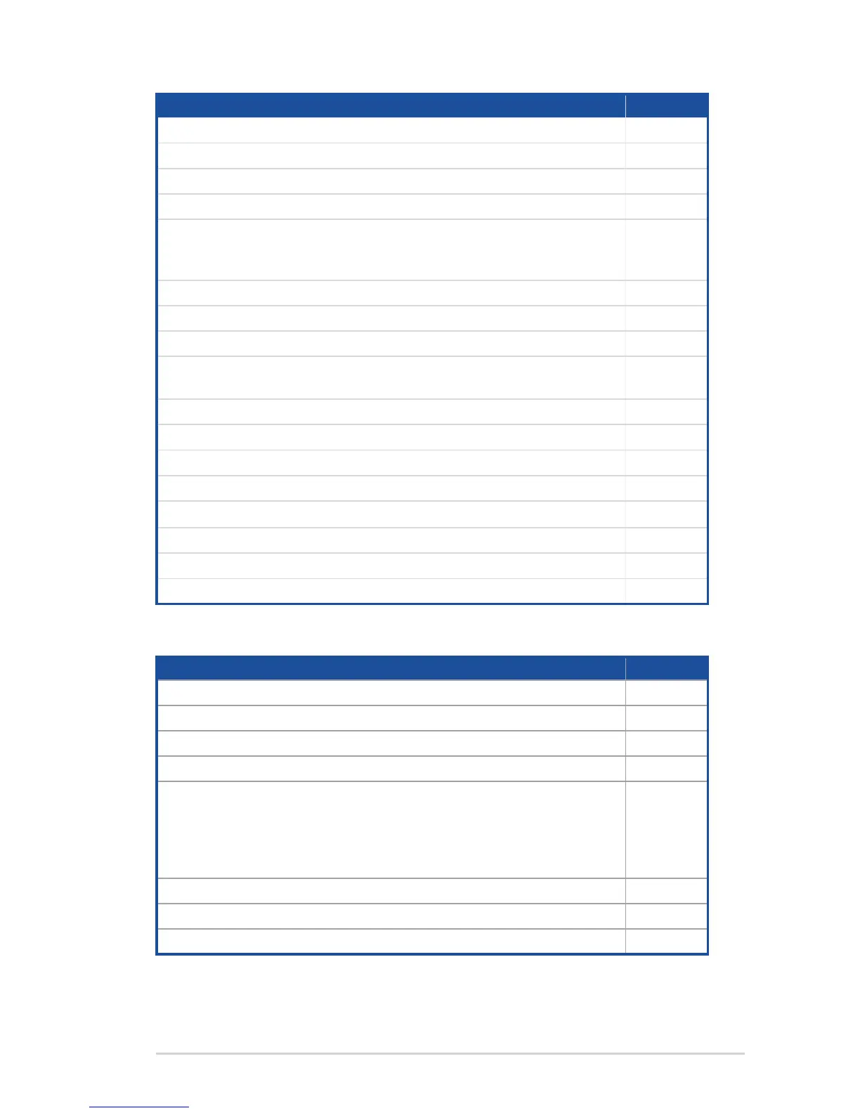
1. Serial ATA 6.0 / 3.0 Gbps connector (7-pin SATA6 [Light Blue]) 4-8
2. PowerSupplySMBusconnector(5-pinPSUSMB1) 4-8
3. USB2.0connector(10-1pinUSB56;USB7) 4-9
4. USB3.0connector(20-1pinUSB3_34) 4-9
5. CPU,front,andrearfanconnectors(4-pinCPU_FAN1,CPU_
FAN2,FRNT_FAN1,FRNT_FAN2,FRNT_FAN3,FRNT_FAN4,
FRNT_FAN5,REAR_FAN1,REAR_FAN2)
4-10
6. LANActivityLEDconnector(5-1pinLAN34_LED1) 4-10
7. Serial port connector (10-1 pin COM1) 4-11
8. TrustedPlatformModuleconnector(20-1pinTPM1) 4-11
9. ATXpowerconnectors(24-pinEATXPWR1,8-pinEATX12V1,
8-pin EATX12V2)
4-12
10. Systempanelconnector(20-1pinPANEL1) 4-13
11. Auxiliarypanelconnector(20-2pinAUX_PANEL1) 4-14
12. VGA connector (10-1 pin VGA_HDR1)
4-15
13. HarddiskactivityLEDconnector(4-pinHDLED1) 4-15
14. ChassisIntrusion(2-pinINTRUSION1)
4-16
15. ISATA&ISSATAconnectors(ISATA;ISSATA) 4-16
16. M.2(NGFF)connector(NGFF1) 4-17
17. MezzaninePCIcardconnector(MEZZ1) 4-17
Onboard LEDs Page
1. StandbyPowerLED(SBPWR1) 4-18
2. Baseboard Management Controller LED (BMCLED1) 4-18
3. CPUWarningLED(ERRCPU1,ERRCPU2) 4-19
4. Location LED (LOCLED1) 4-19
5. Memory error LED (MEMERRA1, MEMERRA2, MEMERRB1,
MEMERRB2, MEMERRC1, MEMERRC2, MEMERRD1,
MEMERRD2,MEMERRE1,MEMERRE2,EMERRF1,
MEMERRF2,MEMERRG1,MEMERRG2,MEMERRH1,
MEMERRH2)
4-20
6. CATT LED (CATTERR_LED1) 4-20
7. Message LED (MESLED1) 4-21
8. OCPLANActivityLEDconnector(4-pinOCP_LED1) 4-21



 To Next Page