ASUS RS500-E8 Series
4-13
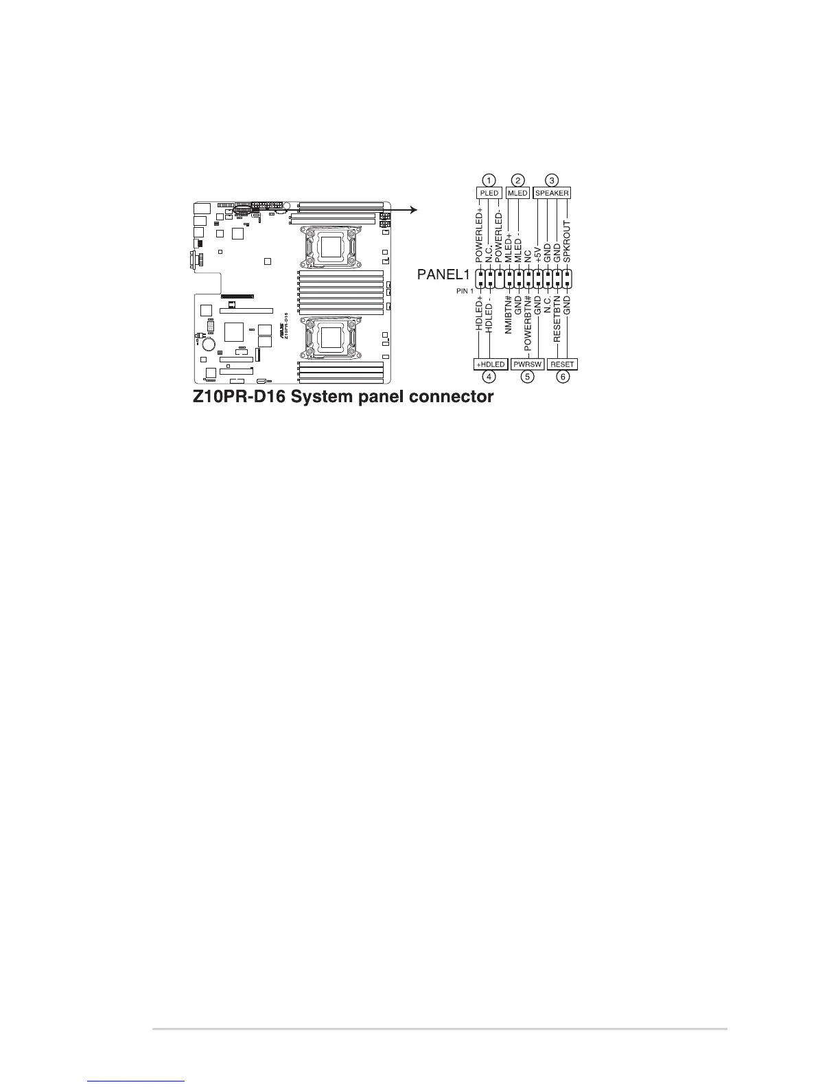
10. System panel connector (20-1 pin PANEL1)
Thisconnectorsupportsseveralchassis-mountedfunctions.
1. System power LED (3-pin PLED)
This3-pinconnectorisforthesystempowerLED.Connectthechassispower
LEDcabletothisconnector.ThesystempowerLEDlightsupwhenyouturnon
thesystempower,andblinkswhenthesystemisinsleepmode.
2. Message LED (2-pin MLED)
This 2-pin connector is for the message LED cable that connects to the front
messageLED.ThemessageLEDiscontrolledbyHardwaremonitortoindicate
anabnormaleventoccurance.
3. System warning speaker (4-pin SPEAKER)
This4-pinconnectorisforthechassis-mountedsystemwarningspeaker.The
speakerallowsyoutohearsystembeepsandwarnings.
4. Hard disk drive activity LED (2-pin +HDLED)
This2-pinconnectorisfortheHDDActivityLED.ConnecttheHDDActivityLED
cabletothisconnector.TheHDLEDlightsuporasheswhendataisreadfrom
orwrittentotheHDD.
5. Power button/soft-off button (2-pin PWRSW)
Thisconnectorisforthesystempowerbutton.Pressingthepowerbuttonturns
thesystemonorputsthesysteminsleeporsoft-offmodedependingontheBIOS
settings.Pressingthepowerswitchformorethanfoursecondswhilethesystem
isONturnsthesystemOFF.
6. Reset button (2-pin RESET)
This 2-pin connector is for the chassis-mounted reset button for system reboot
withoutturningoffthesystempower.