Chapter 3: Motherboard information
3-14
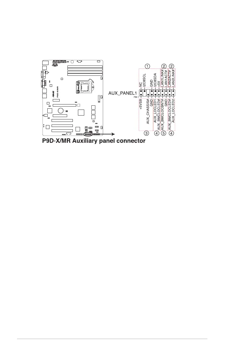
12. Auxiliary panel connector (20-2 pin AUX_PANEL1)
This connector is for additional front panel features including front panel SMB, locator
LEDandswitch,chassisintrusion,andLANLEDs.
1. Front panel SMB (6-1 pin FPSMB)
These leads connect the front panel SMBus cable.
2. LAN activity LED (2-pin LAN1LINK and 2-pin LAN2LINK)
TheseleadsareforGigabitLANactivityLEDsonthefrontpanel.
3. Chassis intrusion (4-1 pin AUX_CHASSIS)
Theseleadsarefortheintrusiondetectionfeatureforchassiswithintrusion
sensorormicroswitch.Whenyouremoveanychassiscomponent,thesensor
triggersandsendsahigh-levelsignaltotheseleadstorecordachassisintrusion
event.ThedefaultsettingisshortCASEOPENandGNDpinbyjumpercapto
disable the function.
4. Locator LED (2-pin AUX_LOCLED1 and 2-pin AUX_LOCLED2)
These leads are for the Locator LED1 and LED2 on the front panel. Connect the
LocatorLEDcablestothese2-pinconnector.TheLEDswilllightupwhenthe
Locator button is pressed.
5. Locator Button/Switch (2-pin AUX_BMCLOCBNT)
Theseleadsareforthelocatorbuttononthefrontpanel.Thisbuttonqueriesthe
state of the system locator.