13/46
4. Hopper vibration/output activation
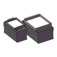
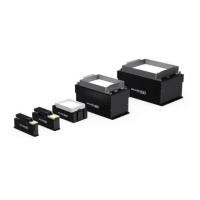
Depending on the Asycube, a hopper is either integrated (Asycube 50 and 80) or not
(Asycube 240, 380 and 530). Therefore, there are some little differences but the general
structure is similar. The following sections describe the organisation of the parameters as well
as the optimal configuration for standard hopper vibrations/output activations.
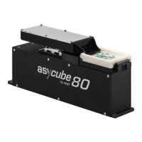
4.1. Asycubes 50 and 80
The Asycubes 50 and 80 have an integrated hopper to feed the necessary number of parts
onto the platform in order to obtain at each cycle an acceptable number of parts available for
picking by a robot. Table 4-1 below lists the parameters that are used to adjust the behaviour
of the hopper.
Amplitude of the signal sent
to the actuator and defined
as the percentage of the
maximum amplitude
Increasing the amplitude
makes the parts jump more.
The frequency of the signal
sent to the actuator
Parts react more at a certain
frequency depending on
different factors
(mass/geometry/rigidity).
Is defined as the shape of
the signal
A sinus waveform form
corresponds to smoother
part movement, whereas
with a ramp form the parts
move more hectically.
0=no signal
1=sinus
2=ramp up
3= ramp down
Amount of time the signal
(i.e. the vibration) lasts
Increasing the duration
makes the part travel a
longer distance on the
hopper (i.e. feeding more
parts). Choosing a value of
0 ms corresponds to
continuous vibration (until
the stop button is pushed).
Table 4-1: Asycube 50 & 80 - Hopper parameters
For more information on the different commands, please refer to the programming guide for
your Asycube.
 Loading...