Installation & Servicing Instructions ATAG Q-Series
20
6.7.1 Dimensioning of the ue gas and air intake duct
The ue diameter is determined by the total length of the run, including for the
connection pipe, elbows ttings and terminal covers etc and the type and number of
boilers installed into the system.
An undersized ue pipe can lead to disorders. Look at table 1 for the choice of the
system and the correct diameter. The table below shows the maximum ue lengths
with the different boiler outputs. A longer ue gas length can be achieved by increasing
the diameter to ø 100mm.
Explanation table 1:
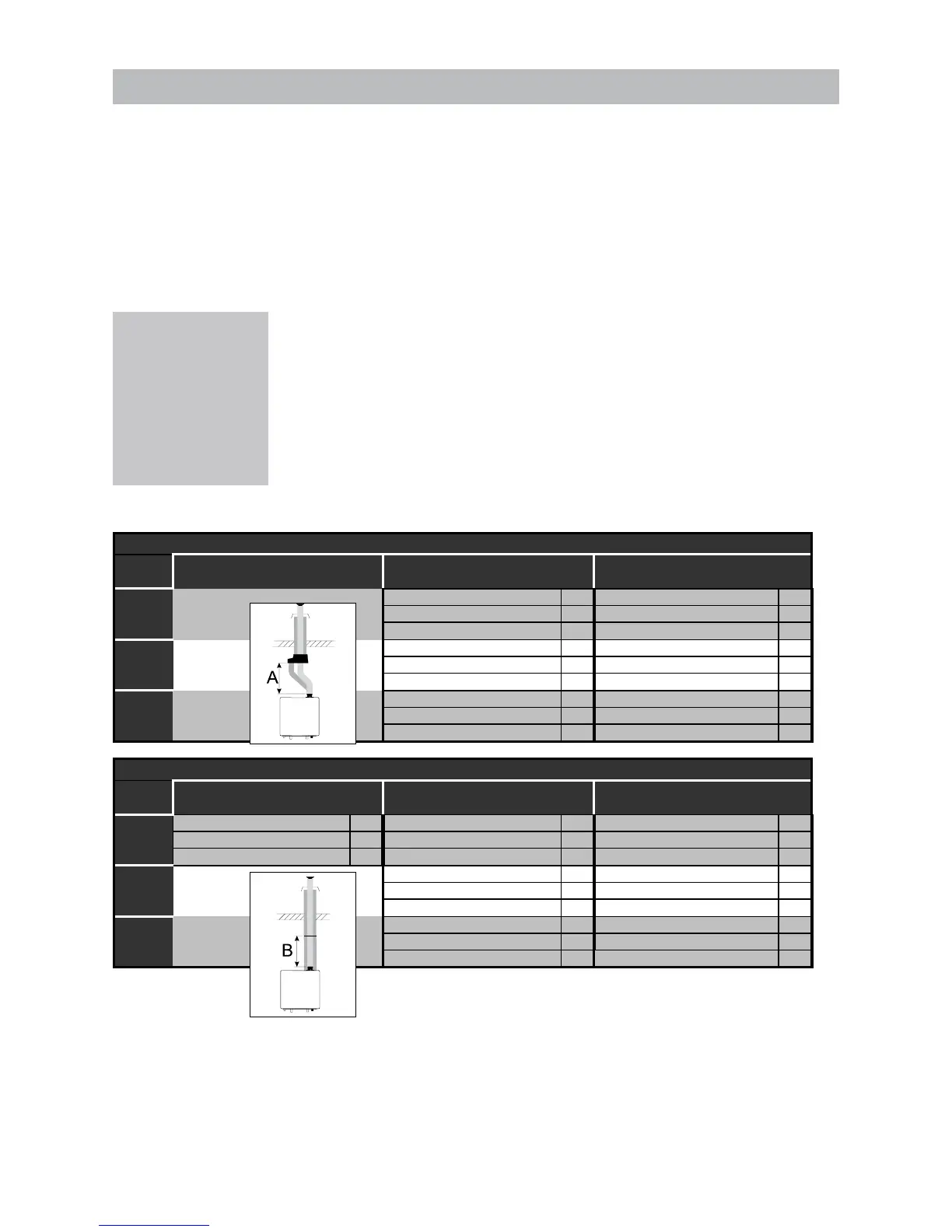
Two pipe ue gas system: maximum noted length = distance between boiler and
roof terminal A
Concentric ue gas system: maximum noted length = distance between boiler and
roof terminal B
When using bends the noted value behind every bend should be deducted from the
maximum straight length.
Pipes with 60/100 diameter are only permitted on wall terminals in
combination with ATAG boilers untill 25kW.
in m
ø100mm
A
in m
16-25 kW Maximum straight lenth 80 31 Maximum straight lenth 100 40
87° bend resistance length -1,5 87° bend resistance length -1,8
45° bend resistance length -0,8 45° bend resistance length -0,9
26-38 kW Maximum straight lenth 80 18 Maximum straight lenth 100 39
87° bend resistance length -1,5 87° bend resistance length -1,8
45° bend resistance length -0,8 45° bend resistance length -0,9
39-60 kW Maximum straight lenth 80 6 Maximum straight lenth 100 18
87° bend resistance length -1,5 87° bend resistance length -1,8
45° bend resistance length -0,8 45° bend resistance length -0,9
ø60/100mm
B
in m
ø80/125mm
B
in m
ø100/150mm
B
in m
16-25 kW Maximum straight lenth 60/100 12 Maximum straight lenth 80/125 31 Maximum straight lenth 100/150 40
87° bend resistance length -1 87° bend resistance length -2,8 87° bend resistance length -2,6
45° bend resistance length -1 45° bend resistance length -1,1 45° bend resistance length -1,1
26-38 kW Maximum straight lenth 80/125 13 Maximum straight lenth 100/150 34
87° bend resistance length -2,8 87° bend resistance length -2,6
45° bend resistance length -1,1 45° bend resistance length -1,1
39-60 kW Maximum straight lenth 80/125 6 Maximum straight lenth 100/150 10
87° bend resistance length -2,8 87° bend resistance length -2,6
45° bend resistance length -1,1 45° bend resistance length -1,1
Concentric flue system
Two pipe flue system + chimney lining
Dimensions ue gas system and air supply system Table 5
Example:
A 25kW with a concentric
ue gas system ø80/125mm
has according to the table a
maximum ue straight length
of 31m In the system that is
going to be put in there are 2
x 45° bends, so the maximum
ue gas length is
31 – ( 2 x 1.1 ) = 28.8 meters.
 Loading...