F1
T1
1 5
4 8
115/230V AC
5V DC
1
2
3
45
67
- +
D1
1
4
3
2
C2
100uF
U1
LM78S05
1
2
3
VIN
GND
VOUT
C1
4700uF
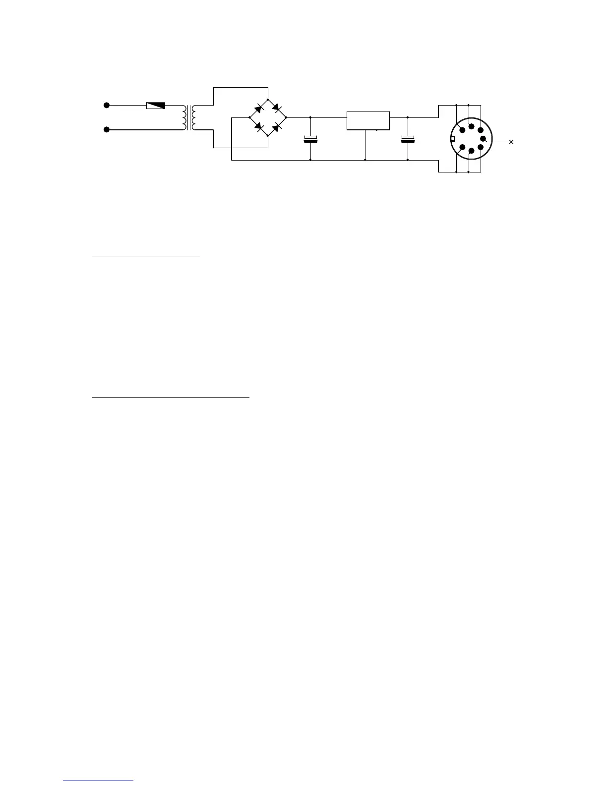
Figure 1-11. External Power Supply Schematic.
The DC output of regulator is 5V ±5% (1.5A Max).
SYSTEM INTERFACE
The 130XE provides the following interfaces:
• The Serial Input/Output (SIO) interface
• The keyboard interface
• The controller jack interface
• The cartridge interface
• The monitor interface
• The LED board interface
Serial Input/Output (SIO) Interface
The Atari 130XE communicates with peripheral devices over an asynchronous serial port
(19.2K Baud Rate Max). Data is transmitted and received as 8 bits of serial data (LSB sent
first) preceded by a logic zero start bit and succeeded by a logic one stop bit. The serial data
out is transmitted as positive logic. The serial DATA OUT line always assumes its new state
when the serial CLOCK OUT line goes high; CLOCK OUT goes low in the center of the
DATA OUT time.
The bus protocol specifies that all commands must originate from the computer, and that
peripherals present data on the bus only when commanded to do so. Every bus operation goes
to completion before another bus operation is initiated (no overlap). An error detected at any
point in the bus operation will abort the entire sequence. A bus operation consists of the
following elements:
Command Frame (From Computer)
Acknowledge Frame (From Peripheral)
Optional Data Frame (To or From Computer)
Complete Frame (From Peripheral)
130XE Personal Computer
Field Service Manual 1-10