Command Frame
The serial bus protocol provides for three types of commands:
1) Data Send
2) Data Receive
3) Immediate (No Data-Command Only)
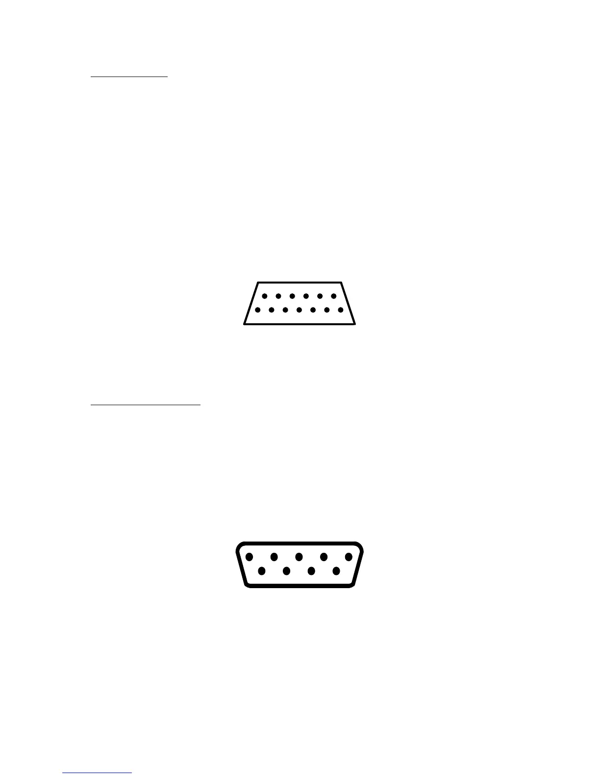
PIN PIN
1 Clock In 7 Command
2 Clock Out 8 Motor Control
3 Data Into CPU 9 Proceed
4 GND 10 Ready (Computer ON)
5 Data Out 11 Audio In (175 mV)
6 GND 12 Not used
13 Interrupt
1
2
3 5 7 9 11 13
4 6 8 10 12
Figure 1-12. SIO Interface Pin Assignments (looking into jack on unit)
External view
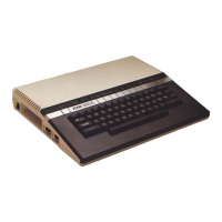
Controller Jack Interface
The 130XE provides two controller jack interfaces. Both are functionally and electrically
identical. The controller jacks are 9-pin D-type connectors.
1. (Joystick) Forward Input 6. Trigger Input
2. (Joystick) Back Input 7. +5 volts
3. (Joystick) Left Input 8. Ground
4. (Joystick) Right Input 9. Pot A Input
5. Pot B Input
1
6
5
9
Figure 1-13. Controller Jack Pin Assignments (from right side of 130XE)
External view
130XE Personal Computer
Field Service Manual 1-11