EasyManuals Logo

Atari 400 Service Manual

Atari 400
129 pages
To Next Page IconTo Next Page
To Previous Page IconTo Previous Page
Page #117 background imageLoading...
Page #117 background image
Remove the plastic Cartridge Guide by unhooking the four
latches from bottom side of Motherboard.
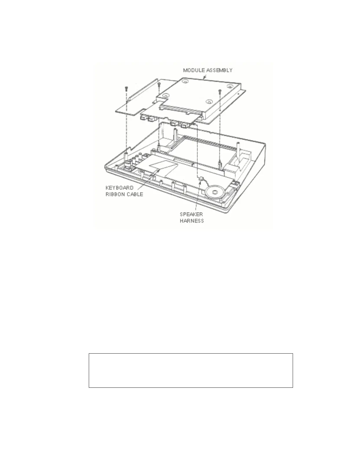
Figure 5-25. 800 Console, Module Assembly Removal
5.7 ASSEMBLY, 400 COMPUTER CONSOLE
The following paragraphs outline the steps required to re-assemble
the 400 Computer Console and its related printed Circuit boards.
1. Module Assembly re-assembly, refer to Figure 5-21
Snap Cartridge Guide into Motherboard (only goes one
way)
Insert RAM Memory bQard and CPU printed circuit board
into Motherboard with compQnent side of PCB to the rear.
Before re-assembling PCBs be sure that they have been
cleaned and lubricatedr refer to paragraph 5.2.1.
CAUTION
Do not allow tip of screwdriver to damage traces
ATARI Personal Computers 5-40

Table of Contents

Other manuals for Atari 400

Questions and Answers:

Question and Answer IconNeed help?

Do you have a question about the Atari 400 and is the answer not in the manual?

Atari 400 Specifications

General IconGeneral
ManufacturerAtari
Model400
TypeHome Computer
Release Year1979
CPUMOS Technology 6502
CPU Speed1.79 MHz
ROM10 KB
Operating SystemAtari OS
KeyboardMembrane keyboard
RAM8 KB (expandable to 48 KB)
GraphicsANTIC and GTIA chips
Sound4 channels
DisplayRF output for connection to TV
StorageOptional cassette tape drive or floppy disk drive
PortsCartridge
Display Resolution320x192 (16 colors)

Related product manuals