After an appropriate delay, the highest seven bits are passed as a
Column Address. Data is then either put in or taken out of the
location selected. Direction of data flow is determined by the
Read/Write line.
Refresh occurs at least every 2 milliseconds. The refresh signal is
generated on the CPU printed circuit board.
4.2.5 Keyboard
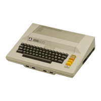
The keyboard generates alphanumeric characters as well as special
graphic symbols. The keyboard allows the operator to communicate with
the Console system for writing programs or responding to
preprogrammed cassettes or cartridges. The keyboard consists of
fifty-seven normally open switches. They are scanned at a rapid rate
and when a switch is found closed, that scan pattern is sent to the
microprocessor for encoding.
4.2.6 Power Supply
The Power Supply printed circuit board receives 9 Vac from an
external power adapter (transformer) and provides +5 Vdc, +12 Vdc,
and -5 Vdc for the Console system. The Power ON/OFF switch is mounted
on the Power Supply pcb and removes input power by opening the 9 Vac
line. An additional interlock switch removes power from the system
when the operator opens the top panel to install or remove Program
Cartridges.
The RF Module also resides on the Power Supply pcb. The RF Module
generates the RF output for the video screen from the composite video
signals received from the Motherboard, and is switchable to
television channel 2 or 3.
Voltages:
+5 Vdc A - Supply voltage for the logic pcbs
+5 Vdc B - Specially filtered for the video circuitry
+12 Vdc and -5 Vdc - Supply voltage for the dynamic RAM memory chips
4.2.7 Program Cartridge
The Program Cartridge performs the function of permanently storing
the microprocessor instructions for a particular application, e.g., a
game or
check book balancing program. It consists of two 4K ROM chips mounted
on an enclosed printed circuit board. Information is retreived from
the ROM chips by addressing the memory locations assigned to the
Program Cartridge slot(s). The data in the memory locations is then
placed on the Data bus lines.
4.3 FUNCTIONAL BLOCK DIAGRAM DISCUSSION
The following paragraphs provide a detailed functional block diagram
discussion of the 400 and 800 Console Systems.
4-4 System Service Manual

 Loading...


