The ATARI 400 and 800 Computer Consoles are general purpose microcom-
puters based upon the 6502 microprocessor. The ATARI 400/800 Con-
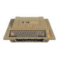
soles, see Figure 1-3, are the central processing units (CPU) for
their respective systems. Each console comes standard with a built in
keyboard. 8K/16K of RAM, ROM operating systems, connector jacks for
adding peripherals and hand controllers, and a 15 foot RF cable for
connection to a user's television set.
The controller jacks on the front of both the 400 and 800 Consoles
accept any of the three types of hand controllers available from
ATARI.
The side panel of the 400 Console, see Figure 1-4, contains a periph-
eral jack, power ON/OFF switch, and a power jack. A channel 2/3
switch is located on the ba ck of the console to switch the console
to channel 2 o r channel 3 transmission frequency.
The side panel of the 800 Console, see Figure 1-5, contains a monitor
jack, a peripheral jack, a channel 2/3 switch, a power ON/OFF switch,
and a power jack.
Both the 400 and 800 Console keyboards provide a full alphanumeric
character set, cursor controls, and special purpose keys. The alpha-
bet keys when used in conjunction with the CTRL (Control) key become
special graphic symbols. To the right of the keyboard is the power ON
light and four special control switches. From top to bottom they are:
SYSTEM RESET - Interrupts whatever the computer is doing and restarts
the Operating System or Program Cartridge
OPTION - Interrupt used by the Program Cartridge to choose amoung the
variations within a game or program
SELECT - Interrupt used to select one of several games or
programs in the Program Cartridge
START - Interrupt used to Start the game or program selected from the
Program Cartridge
The AC Power Adapter provides the 9 Vac used by the 400 and 800 Com-
puter Consoles. The AC Power Adapter plugs into a standard wall out-
let and converts the 110V ac line voltage to the 9V ac required by
the Consoles. The power cord from the AC Power Adapter plugs into the
power jack on either the 400 or 800 Console.
The TV Switch Box allows the 400/800 Computer Console to be connected
to the normal 300 ohm RF antenna inputs on a typical television set.
The Proqram Cassette Recorder provides 400K bytes of storage (120
ATARI Personal Computers 1-7