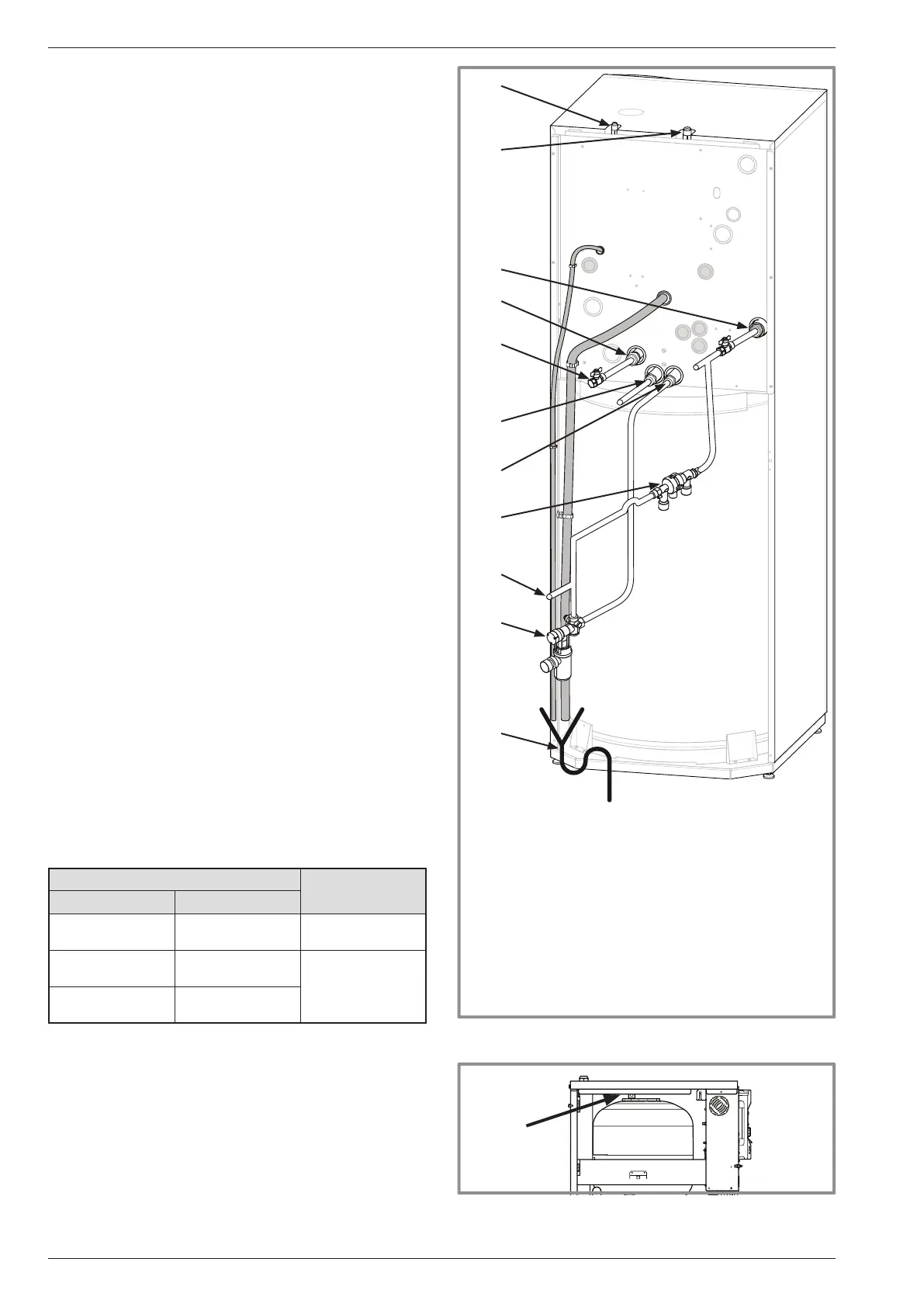
gure 25 - Connections
1
2
3
5
4
6
7
8
9
10
11
Legend:
1. "Liquid" refrigeration connection.
2. "Gas" refrigeration connection .
3. Heating return (1 circuit).
4. Heating ow (1 circuit).
5. Stop valve (not supplied).
6. DHW exit (domestic hot water).
7. DCW entry (domestic cold water).
8. Shut-off (not supplied).
9. Filling.
10. Safety unit (not supplied).
11. Connecting to the drain with the siphon.
- Bleed tap evacuation.
- Safety valve evacuation.
gure 26 - Hydraulic
module bleeder valve
P
2.8.3 Rinsing out the installation
Before connecting the hydraulic unit to the installation,
rinse out the heating system correctly to eliminate
any particles that may affect the appliance's correct
operation.
Do not use solvents or aromatic hydrocarbons (petrol,
paraf n, etc.).
In the case of an old installation, provide a suf ciently
large decanting pot with a drain on the return from the
boiler and at the lowest point in the system in order to
collect and remove the impurities.
Add an alkaline product to the water and a dispersant.
Rinse the installation several times before lling it
de nitively.
2.8.4 Filling and purging the installation
Check the pipe xings, the tightness of the connectors
and the stability of the appliance.
Check the direction in which the water is circulating and
that all the valves open.
Proceed to ll the installation.
Do not operate the circulating pump while lling. Open all
the drain valves in the installation and the bleeder valve
for the hydraulic unit (P) to remove the air contained in
the conduits.
Close the drain and bleeder valves and add water until
the pressure in the hydraulic circuit reaches 1 bars.
Check that the hydraulic circuit has been purged correctly.
Check there is not a leak.
After the "Commissioning", page 34, once the
machine has started, purge the hydraulic unit again
(2 litres of water).
" Precise lling pressure is determined by the
manometric height of the installation.
2.8.5 Connecting the Fan convector
or dynamic radiator circuit
For all Heat Pump > 11 kW: It must be installed
on return of this circuit a buffer tank (minimum
capacity: 100 liters) (see "Overall hydraulic layout",
page 54).
Circuit...
with HP > 11 kW
...mixed (CC1) ...direct (CC2)
Heating-cooling
oor
Dynamic radiator
or Fan convector
Buffer Tank on the
return CC2
Dynamic radiator
or Fan convector
Radiators
Buffer Tank
on the return
of each circuits
Dynamic radiator
or Fan convector
Dynamic radiator
or Fan convector
Installation and operating manual "1578 - EN"
Heat Pump alféa extensa duo +
- 24 -



 To Next Page