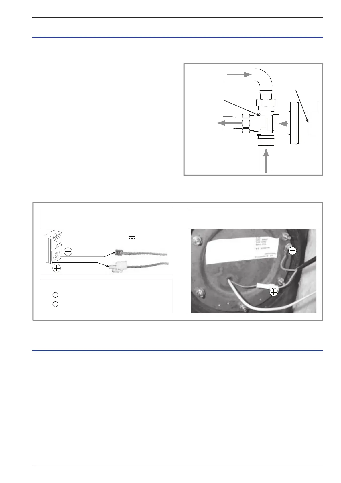
B
A
AB
Inlet to the
Exchanger
Heating circuit
return
gure 49 - Fitting the distribution valve
Return from DHW tank
Valve
Valve motor
8 Maintenance
8.1 Emptying the hydraulic unit
- Remove the facade from the hydraulic unit.
- Place the distribution valve in the middle position.
- Open the emptying valve (ref. 5).
- Open the hydraulic unit’s manual bleed-tap (ref. 6).
- Open the installation bleed tap.
8.2 Distribution valve
Carefully comply with the direction for tting the
distribution valve:
Channel AB : Inlet to the exchanger (hydraulic unit).
Open channel A : Return from DHW tank.
Open channel B : Return from the heating circuit.
8.3 ACI check
- Check polarity.
- Check voltage: The appliance powered on, the
voltage value must be positive and lie between 0 + and
+ 6.5 V dc.
9 Instructions for the user
Explain to the user how his installation operates, in
particular the functions of the room thermostat and the
programmes accessible to him from the user interface.
U = + 0 + 6,5 V
Check ACI voltage Connecting
ACI connecting:
The on the tank mass.
The on the electrode connector.
-
+
to
gure 50 - ACI check
Emphasise that a heated oor has signi cant inertia
and that therefore any adjustments must be made
progressively.
Also explain to the user how to check the lling of the
heating circuit.
Installation and operating manual "1578 - EN" - 63 -
Heat Pump alféa extensa duo +
 Loading...